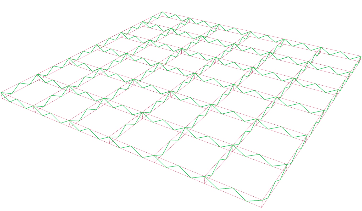
In this tutorial, we will create a truss grid. For this, we need a basic grid
pattern and trussed girders along the axes of the grid. Meanwhile, we learn
common operations with data trees
Grasshopper
1
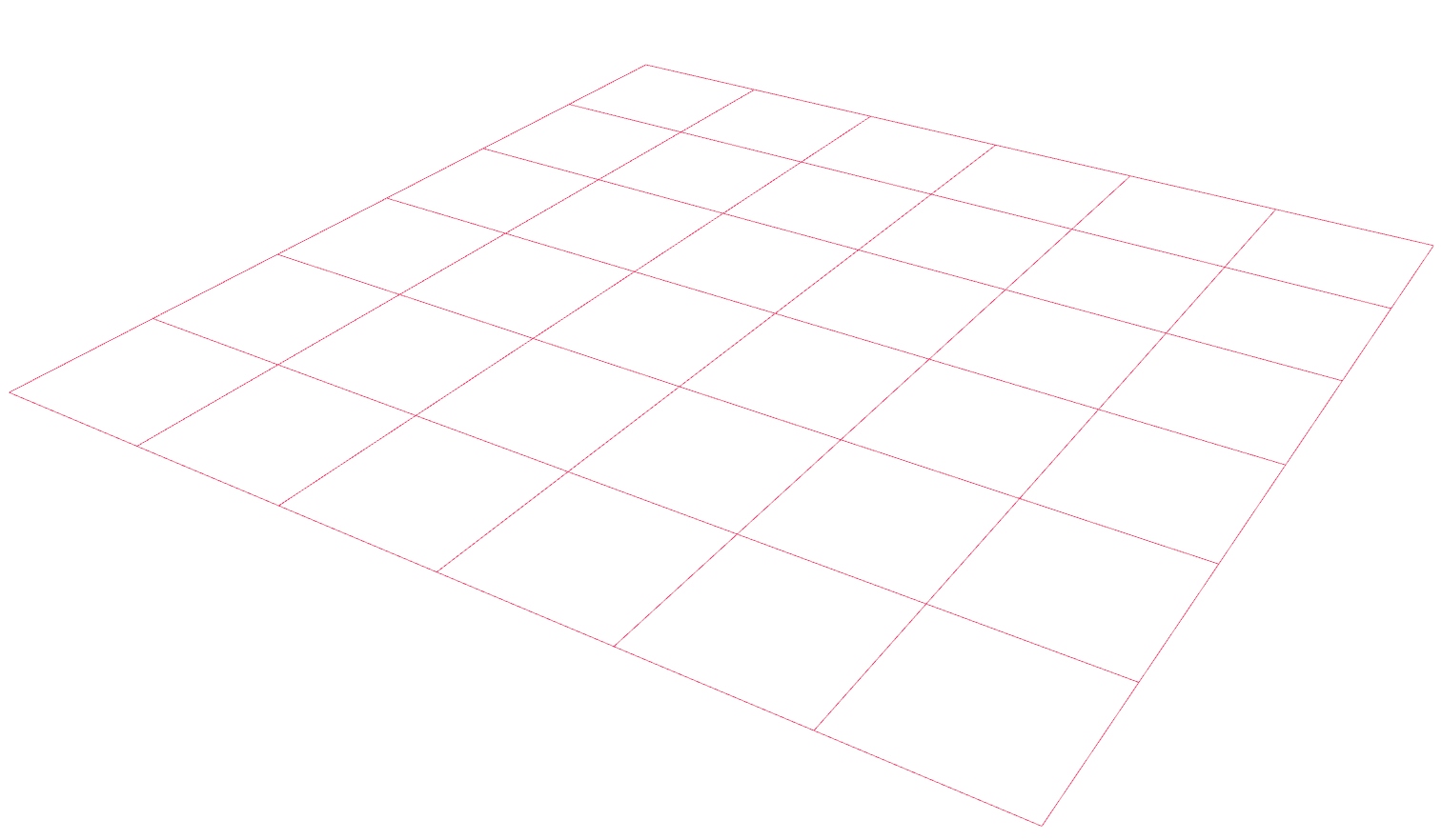
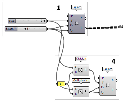
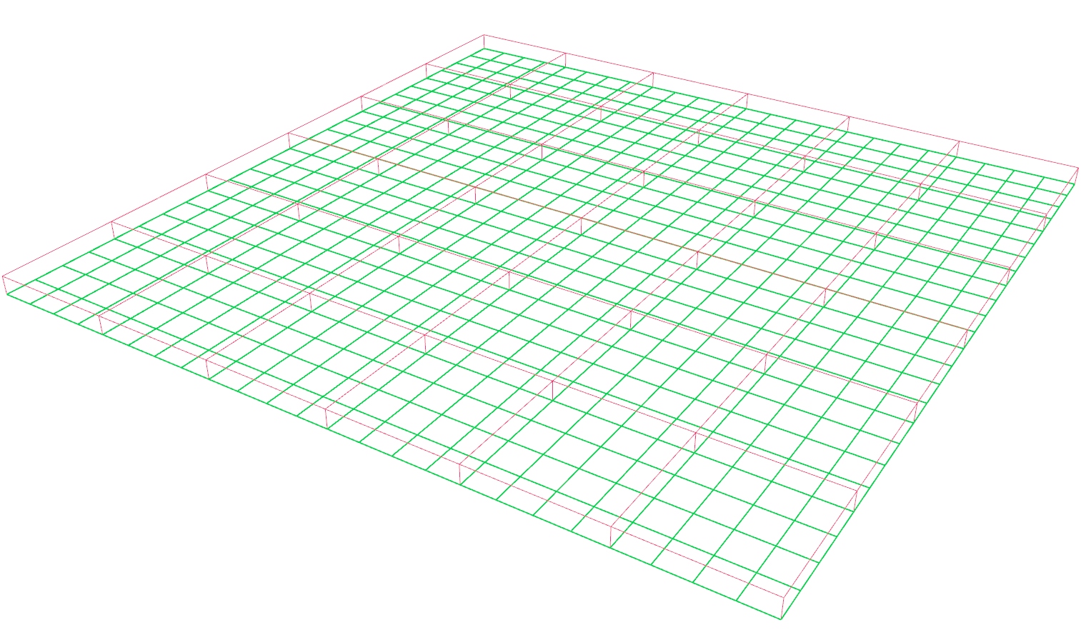
Generate a basic grid pattern
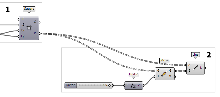
First thing to do, is to create the basic grid. For this, we use a Square Square (SqGrid)
Inputs Plane (P) Base plane for grid Size (S) Size of grid cells Extent X (Ex) Number of grid cells in base plane x direction Extent Y (Ey) Number of grid cells in base plane y direction Outputs Cells (C) Grid cell outlines Points (P) Points at grid corners
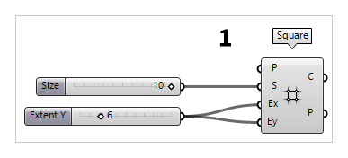
Now, lets change the slider output to whole numbers:
After creating a Number Slider Number Slider
5 and a Max of 10. Now the slider will return whole numbers within the set
range. We connect this slider to input S.
Another way to create a slider that returns integers in a given range, is to use
the Canvas search and type 2..20. After pressing
Enter a slider is placed on the canvas that ranges from 2 to 20
and we connect it to the inputs Ex and Ey.
2
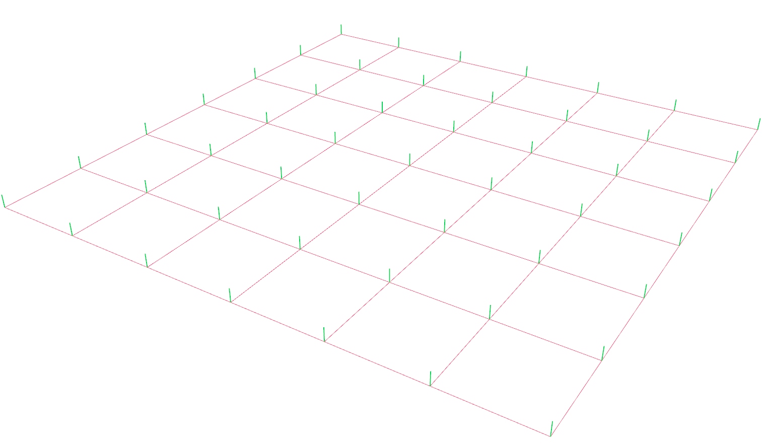
Create the vertical members
After generating the basic grid, we get its corner points at output P. To
create the vertical members, we need to create a second set of points above our
basic grid. For this, we use a Move Move (Move)
Inputs Geometry (G) Base geometry Motion (T) Translation vector Outputs Geometry (G) Translated geometry Transform (X) Transformation data
The translation vector is defined with a Unit Z Unit Z (Z)
Inputs Factor (F) Unit multiplication Outputs Unit vector (V) World {z} vector 0.5..1.5 into the Canvas Search, we get a Number Slider
Number Slider
To create the vertical members, we use a Line Line (Ln)
Inputs Start Point (A) Line start point End Point (B) Line end point Outputs Line (L) Line segment
3
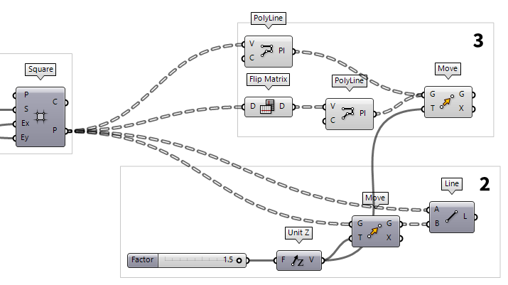
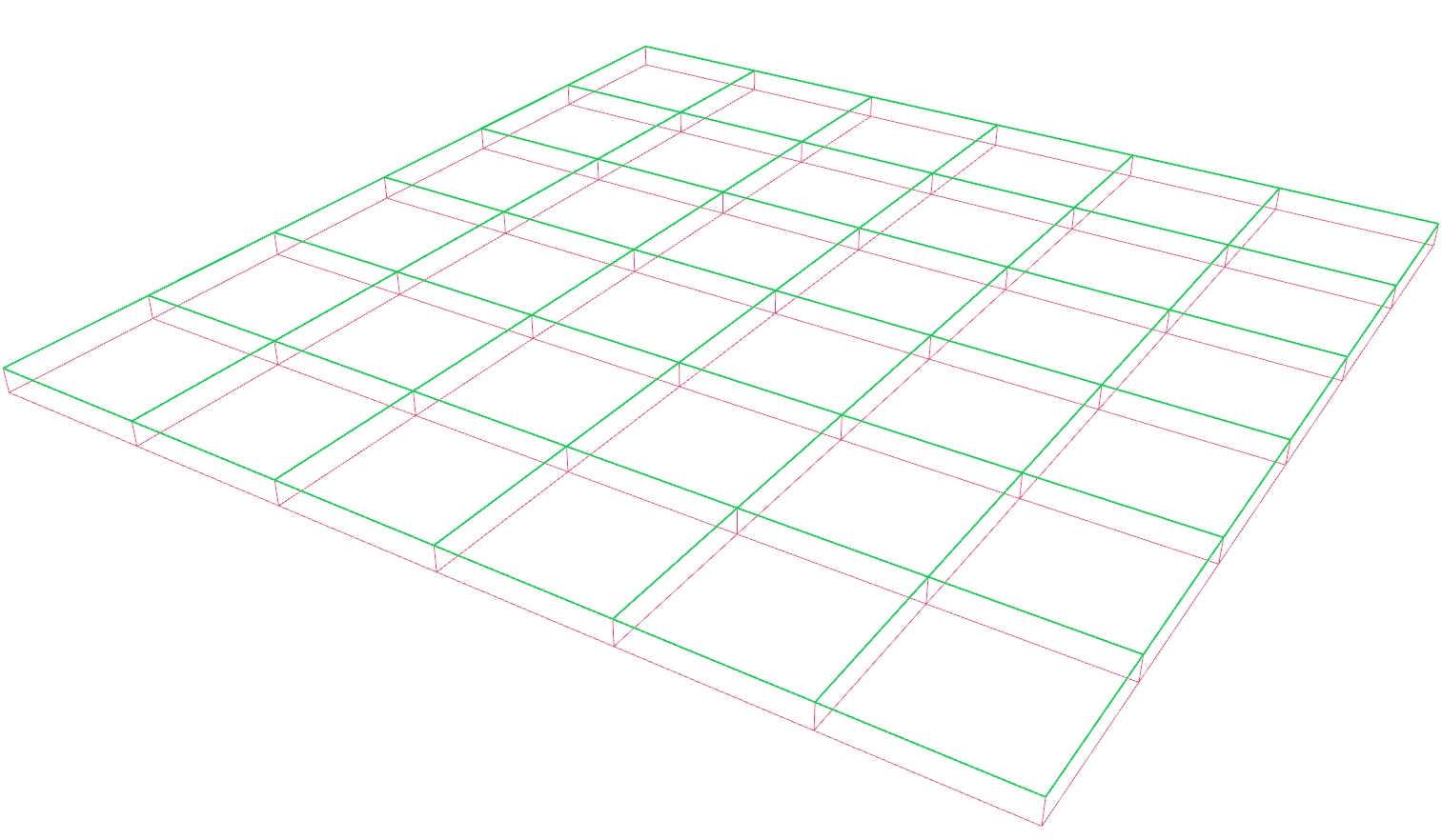
Create the upper and lower chords
At output P of the grid, the points at the grid corners are structured in a
data tree format PolyLine (PLine)
Inputs Vertices (V) Polyline vertex points Closed (C) Close polyline Outputs Polyline (Pl) Resulting polyline
To create lines in the row direction, we need to change the structure of the
data tree by using a Flip Matrix Flip Matrix (Flip)
Inputs Data (D) Data matrix to flip Outputs Data (D) Flipped data matrix
PolyLine (PLine)Inputs Vertices (V) Polyline vertex points Closed (C) Close polyline Outputs Polyline (Pl) Resulting polyline
The just created polylines represent the lower chords of our truss grid and we
need another Move
Move (Move)Inputs Geometry (G) Base geometry Motion (T) Translation vector Outputs Geometry (G) Translated geometry Transform (X) Transformation data
4
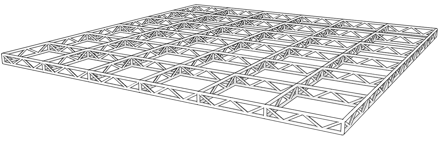
Generate a sub grid
The next thing we want to create are the diagonal members. Here, we don’t want the diagonals to run between the points from before, but in a zigzag with a higher frequency (as shown in the sketch).
To find the points for the higher frequency, we will use another Square
Square (SqGrid)Inputs Plane (P) Base plane for grid Size (S) Size of grid cells Extent X (Ex) Number of grid cells in base plane x direction Extent Y (Ey) Number of grid cells in base plane y direction Outputs Cells (C) Grid cell outlines Points (P) Points at grid corners  Division (A/B)
Inputs A (A) Item to divide (dividend) B (B) Item to divide with (divisor) Outputs Result (R) The result of the Division  Panel
Panel4. Now 4 cells of the sub grid span the distance of one cell from the main
grid.
Because the cells of the sub grid are smaller, we need more of them to cover the
area of the main grid: We use a Multiplication Multiplication (A×B)
Inputs A (A) First item for multiplication B (B) Second item for multiplication Outputs Result (R) Result of multiplication 4.
5
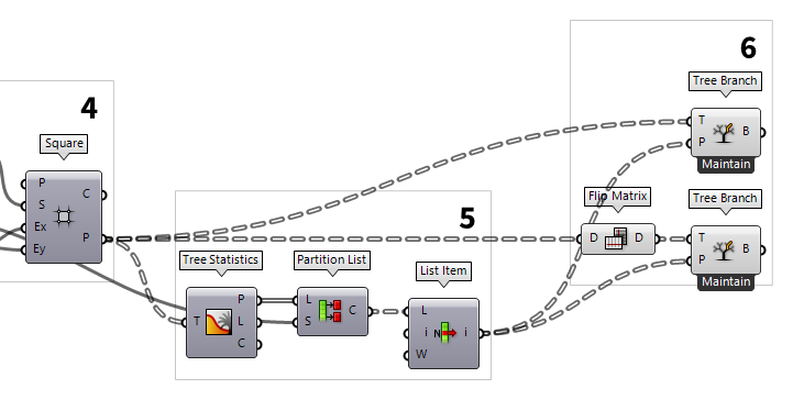
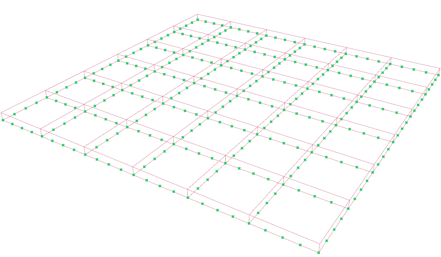
Identify the needed points from the sub grid
The output P returns all the points at the sub grid corners, however, we only
need those that are on the axes of the main grid. We could either find them by
analyzing their geometric location or by selecting the desired branches by name.
In this example, we retrieve the points by doing the latter. To get the names of
the branches, we hook up a Tree Statistics Tree Statistics (TStat)
Inputs Tree (T) Data Tree to analyze Outputs Paths (P) All the paths of the tree Length (L) The length of each branch in the tree Count (C) Number of paths and branches in the tree
The names of the branches can be found at output P. Now, we need every
fourth branch (or to be more precise, the first, then the fifth etc). To
get every fourth name, we use a Partition List Partition List (Partition)
Inputs List (L) List to partition Size (S) Size of partitions Outputs Chunks (C) List chunks 4 to input S. This
will chop the list of names into branches with four items each. Connecting a List Item List Item (Item)
Inputs List (L) Base list Index (i) Item index Wrap (W) Wrap index to list bounds Outputs Item (i) Item at {i'}

6
Extract the needed sub points
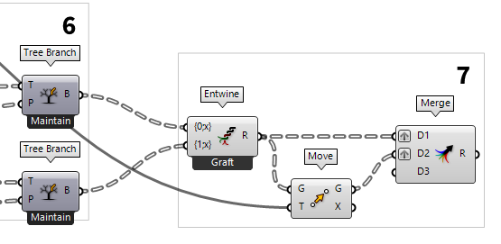
Now that we have the names for the branches we want, we use a Tree Branch Tree Branch (Branch)
Inputs Tree (T) Data Tree Path (P) Data tree branch path Outputs Branch (B) Branch at {P}
We also need the rows of the sub grid that are on the main grid. To get them, we
need to use a Flip Matrix
Flip Matrix (Flip)Inputs Data (D) Data matrix to flip Outputs Data (D) Flipped data matrix
Tree Branch (Branch)Inputs Tree (T) Data Tree Path (P) Data tree branch path Outputs Branch (B) Branch at {P}
7
Move and pair the sub points
With the completion of step 6, we have the desired points from the sub grid.
But, the column and row direction are separated in two components. We will now
combine them into a single data tree, so that we can move the whole tree of
points instead of two individual trees. To combine different trees into one
tree, on which each branch contains an old tree, we will use the Entwine Entwine (Entwine)
Inputs Branch {0;0} ({0;0}) Data to entwine Branch {0;1} ({0;1}) Data to entwine Branch {0;2} ({0;2}) Data to entwine Outputs Result (R) Entwined result
After connecting each direction of points to its own input, we zoom in until
we see the zoomable user interface and then press the
little minus to remove the spare input. Now, we use another Move
Move (Move)Inputs Geometry (G) Base geometry Motion (T) Translation vector Outputs Geometry (G) Translated geometry Transform (X) Transformation data
Next, we want to combine the two sets of sub points into a data tree. But this
time, we want branches that contain the two points that are on top of each
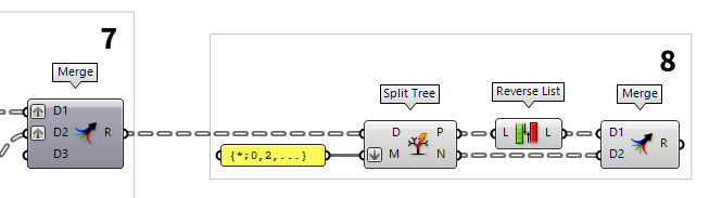
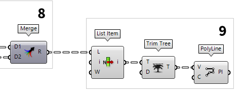
other. Placing a Merge Merge (Merge)
Inputs Data 1 (D1) Data stream 1 Data 2 (D2) Data stream 2 Outputs Result (R) Result of merge
8
Flip every second pair of points
To run the zigzag for the diagonals, we will flip the order of every second pair
of points. To select every second branch, we use a Split Tree Split Tree (Split)
Inputs Data (D) Tree to split Masks (M) Splitting masks Outputs Positive (P) Positive set of data (all branches that match any of the masks) Negative (N) Negative set of data (all branches that do not match any of the masks
Panel{*;0,2,...}. This pattern will select all
branches that end with in even number.
To flip the order of the positive matches, we use a Reverse List Reverse List (Rev)
Inputs List (L) Base list Outputs List (L) Reversed list
Merge (Merge)Inputs Data 1 (D1) Data stream 1 Data 2 (D2) Data stream 2 Outputs Result (R) Result of merge
9
Create the diagonal members
After step 8, we have lists in which the first item is alternately on the lower
and upper chord. Now, we will create a polyline that connects every first point.
To grab the first item from a list, we use List Item
List Item (Item)Inputs List (L) Base list Index (i) Item index Wrap (W) Wrap index to list bounds Outputs Item (i) Item at {i'}  Trim Tree (Trim)
Inputs Tree (T) Data tree to flatten Depth (D) Number of outermost branches to merge Outputs Tree (T) Trimmed data tree
Finally, we connect a PolyLine
PolyLine (PLine)Inputs Vertices (V) Polyline vertex points Closed (C) Close polyline Outputs Polyline (Pl) Resulting polyline
Test your skills
Well, the above was certainly fun because the algorithm now includes all kinds
of data tree operations, but of course, there is a quicker way, especially for
creating the zigzag. We can, for example, not only use Split Tree
Split Tree (Split)Inputs Data (D) Tree to split Masks (M) Splitting masks Outputs Positive (P) Positive set of data (all branches that match any of the masks) Negative (N) Negative set of data (all branches that do not match any of the masks
Extract the needed sub points
As said, we can use Split
Tree to select the branches we need from the sub gird. But, before we do that,
we should use a Flip Matrix
Flip Matrix (Flip)Inputs Data (D) Data matrix to flip Outputs Data (D) Flipped data matrix
Entwine (Entwine)Inputs Branch {0;0} ({0;0}) Data to entwine Branch {0;1} ({0;1}) Data to entwine Branch {0;2} ({0;2}) Data to entwine Outputs Result (R) Entwined result
Then we can use the Split Tree
Split Tree (Split)Inputs Data (D) Tree to split Masks (M) Splitting masks Outputs Positive (P) Positive set of data (all branches that match any of the masks) Negative (N) Negative set of data (all branches that do not match any of the masks {*;0,4,...}, which selects every fifth branch from the sub grid. Using Move
Move (Move)Inputs Geometry (G) Base geometry Motion (T) Translation vector Outputs Geometry (G) Translated geometry Transform (X) Transformation data
PolyLine (PLine)Inputs Vertices (V) Polyline vertex points Closed (C) Close polyline Outputs Polyline (Pl) Resulting polyline

Combine the points
There are different ways to combine the points for creating the diagonal members. You can do it either way.
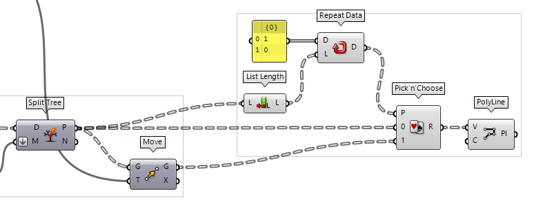
Pick’n’Choose
We could use Pick'n'Choose Pick'n'Choose (P'n'C)
Inputs Pattern (P) Pick pattern of input indices Stream 0 (0) Input stream 0 Stream 1 (1) Input stream 1 Outputs Result (R) Picked result
Panel1 and 0 (make sure to untoggle Multiline Data in the context menu
of the panel).
Pick’n’Choose will not repeat the pattern internally and thus, we have to add
a Repeat Data Repeat Data (Repeat)
Inputs Data (D) Pattern to repeat Length (L) Length of final pattern Outputs Data (D) Repeated data  List Length (Lng)
Inputs List (L) Base list Outputs Length (L) Number of items in L
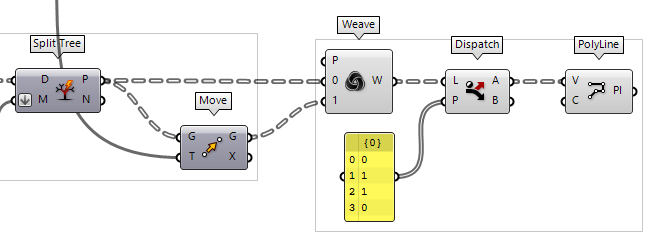
Weave and Dispatch
We could also use the Weave Weave (Weave)
Inputs Pattern (P) Weave pattern of input indices Stream 0 (0) Input stream 0 Stream 1 (1) Input stream 1 Outputs Weave (W) Weave result
Given this pattern, we just need to grab the desired points, which we do with a
Dispatch Dispatch (Dispatch)
Inputs List (L) List to filter Dispatch pattern (P) Dispatch pattern Outputs List A (A) Dispatch target for True values List B (B) Dispatch target for False values 0, 1, 1, 0 (untoggle Multiline
Data). Output A returns the remaining points that we are looking for.
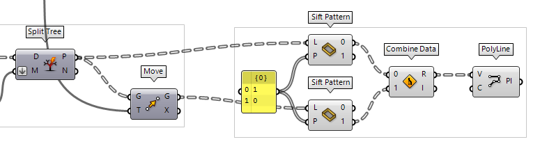
Sift Pattern and Combine Data
Unlike with Weave, where we reduced the number of points after combining them,
we can also reduce the unnecessary points before combining. We do this with Sift Pattern Sift Pattern (Sift)
Inputs List (L) List to sift Sift Pattern (P) Sifting pattern Outputs Output 0 (0) Output for sift index 0 Output 1 (1) Output for sift index 1 1 and 0 again and connect it to
one Sift Pattern for the lower chords and one for the upper chords.
To combine them, we use Combine Data Combine Data (Combine)
Inputs Input 0 (0) Data to combine Input 1 (1) Data to combine Outputs Result (R) Resulting data with as few nulls as possible Index (I) Index of input that was copied into result