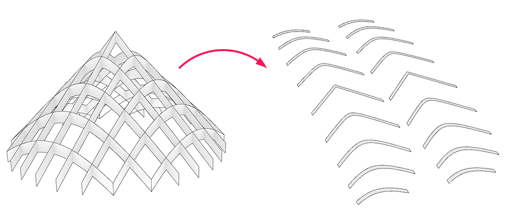
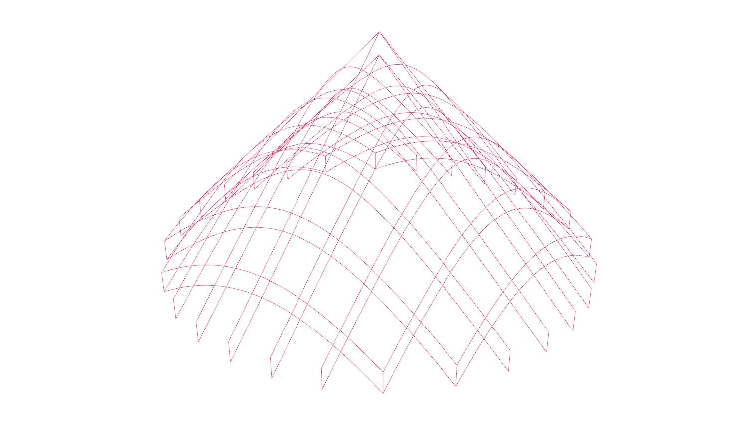
In this tutorial, we will generate slices from a 3d model and arrange them next to each other in one layer. This approach will work with any three-dimensional object; here we use a cone. The slices result from an intersection of the model with an array of planes. The generated section curves could be used for plotting or a CNC router.
Grasshopper
1
Define initial geometric object
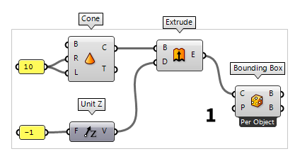
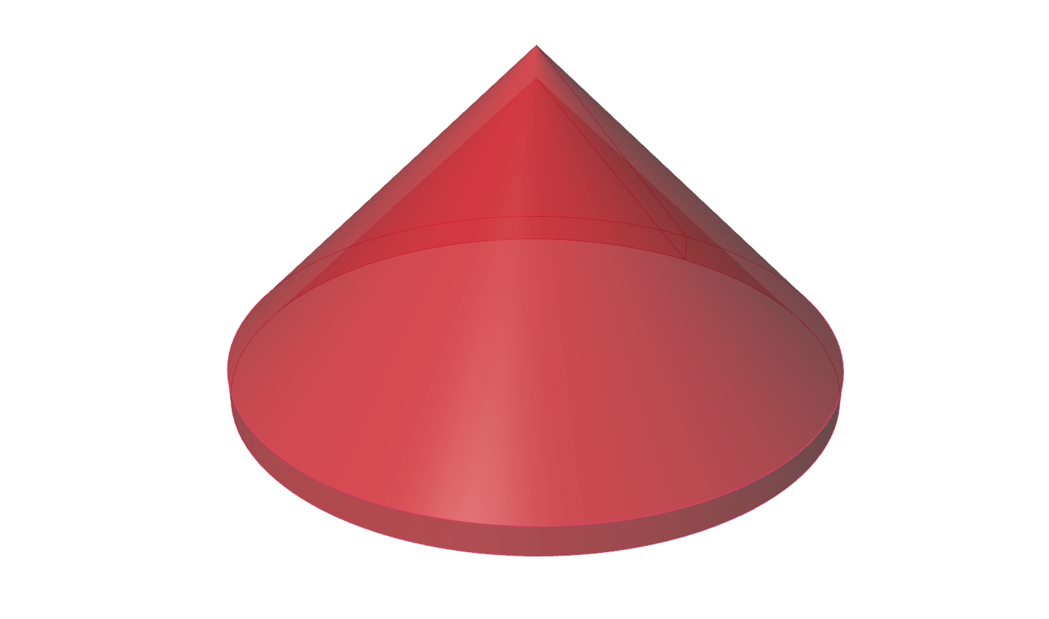
To start, we need a shape and in the following we will use a cone to illustrate
the procedure. Thus, we place a Cone Cone (Cone)
Inputs Base (B) Base plane Radius (R) Radius at cone base Length (L) Cone height Outputs Cone (C) Resulting cone Tip (T) Tip of cone 10 to the radius R and length L. By attaching an Extrude Extrude (Extr)
Inputs Base (B) Profile curve or surface Direction (D) Extrusion direction Outputs Extrusion (E) Extrusion result  Unit Z (Z)
Inputs Factor (F) Unit multiplication Outputs Unit vector (V) World {z} vector -1. A Bounding Box Bounding Box (BBox)
Inputs Content (C) Geometry to contain Plane (P) BoundingBox orientation plane Outputs Box (B) Aligned bounding box in world coordinates Box (B) Bounding box in orientation plane coordinates
Bounding Box (BBox)Inputs Content (C) Geometry to contain Plane (P) BoundingBox orientation plane Outputs Box (B) Aligned bounding box in world coordinates Box (B) Bounding box in orientation plane coordinates
Bounding Box (BBox)Inputs Content (C) Geometry to contain Plane (P) BoundingBox orientation plane Outputs Box (B) Aligned bounding box in world coordinates Box (B) Bounding box in orientation plane coordinates
2
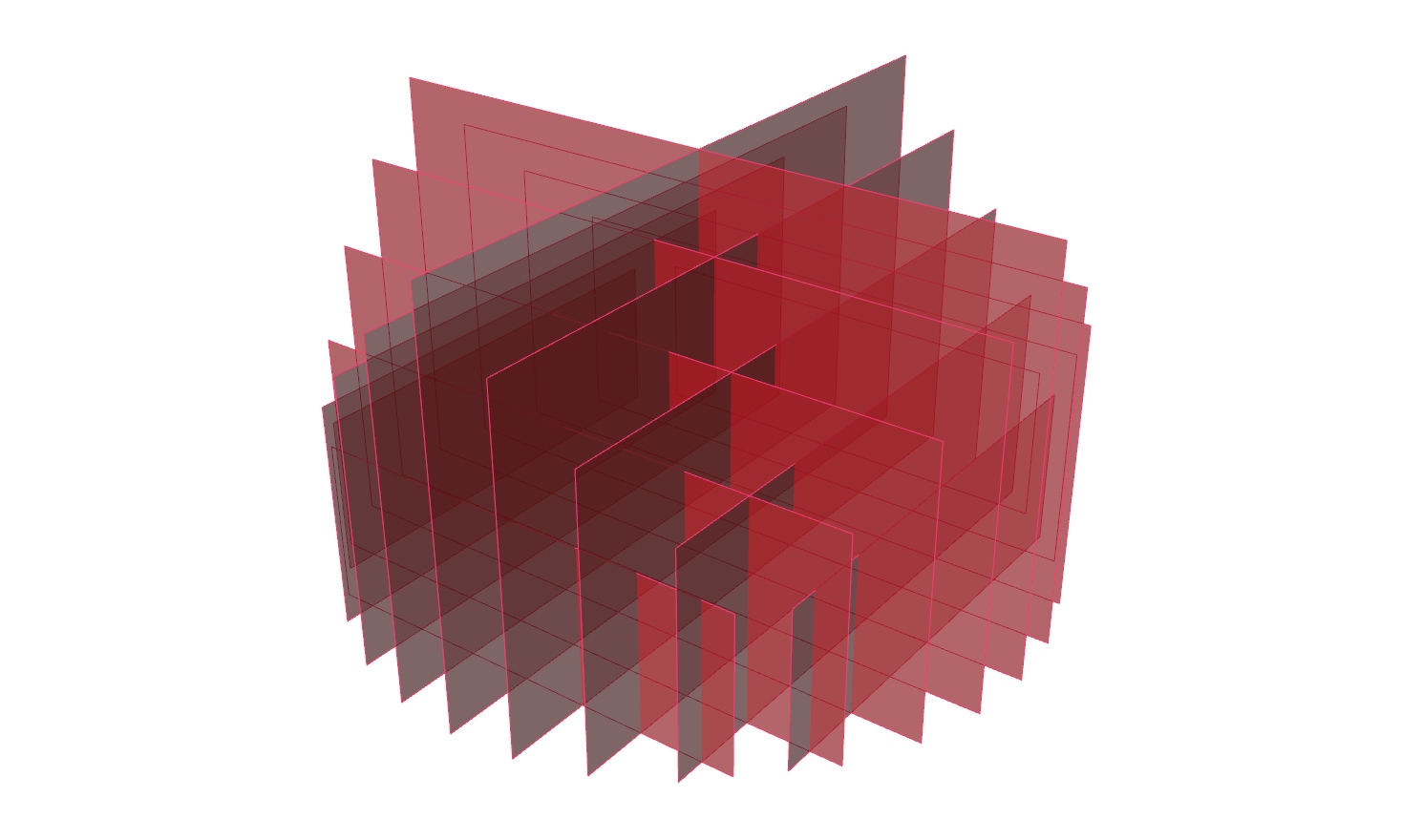
Generate section planes
To define section planes, we need an array of points that serve as origins for
the planes. To find these points, we use Evaluate Box Evaluate Box (Box)
Inputs Box (B) Base box U parameter (U) {u} parameter (values between 0.0 and 1.0 are inside the box) V parameter (V) {v} parameter (values between 0.0 and 1.0 are inside the box) W parameter (W) {w} parameter (values between 0.0 and 1.0 are inside the box) Outputs Plane (Pl) Plane at {uvw} coordinate Point (Pt) Point at {uvw} coordinate Include (I) True if point is inside or on box
The component Range Range (Range)
Inputs Domain (D) Domain of numeric range Steps (N) Number of steps Outputs Range (R) Range of numbers 0 To 1 and 10 ascending values are created.
This is good enough for this exercise, but we need to use Cull Index Cull Index (Cull i)
Inputs List (L) List to cull Indices (I) Culling indices Wrap (W) Wrap indices to list range Outputs List (L) Culled list  YZ Plane (YZ)
Inputs Origin (O) Origin of plane Outputs Plane (P) World YZ plane  XZ Plane (XZ)
Inputs Origin (O) Origin of plane Outputs Plane (P) World XZ plane

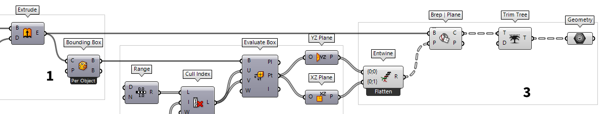
3
Compute section curves
While working with a Grasshopper algorithm, we have to ensure the data
structures match the planed operation. In this case, we need a data tree Entwine (Entwine)
Inputs Branch {0;0} ({0;0}) Data to entwine Branch {0;1} ({0;1}) Data to entwine Branch {0;2} ({0;2}) Data to entwine Outputs Result (R) Entwined result
Next, we place a Brep | Plane Brep | Plane (Sec)
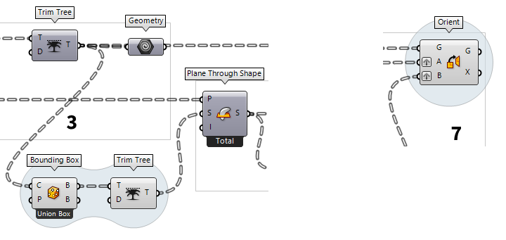
Inputs Brep (B) Base Brep Plane (P) Section plane Outputs Curves (C) Section curves Points (P) Section points  Trim Tree (Trim)
Inputs Tree (T) Data tree to flatten Depth (D) Number of outermost branches to merge Outputs Tree (T) Trimmed data tree  Geometry (Geo)
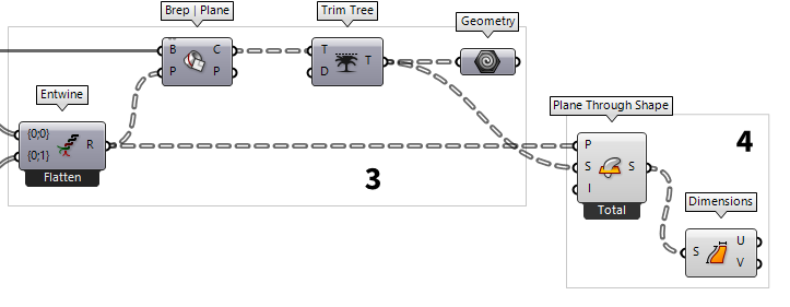
4
Get dimensions for arranging the curves in a plane
In the second half of this tutorial, we will arrange the slices in a single
plane and next to each other, thus preparing them to be plotted on a sheet of
paper. For this, we need coordinates for each slice that prevent overlapping of
section curves. To get the dimensions, we use Plane Through Shape Plane Through Shape (PxS)
Inputs Plane (P) Surface plane Shape (S) Shape to exceed Inflate (I) Boundary inflation amount Outputs Surface (S) Resulting planar surface
Plane Through Shape (PxS)Inputs Plane (P) Surface plane Shape (S) Shape to exceed Inflate (I) Boundary inflation amount Outputs Surface (S) Resulting planar surface
Bounding Box (BBox)Inputs Content (C) Geometry to contain Plane (P) BoundingBox orientation plane Outputs Box (B) Aligned bounding box in world coordinates Box (B) Bounding box in orientation plane coordinates
Plane Through Shape (PxS)Inputs Plane (P) Surface plane Shape (S) Shape to exceed Inflate (I) Boundary inflation amount Outputs Surface (S) Resulting planar surface
Bounding Box (BBox)Inputs Content (C) Geometry to contain Plane (P) BoundingBox orientation plane Outputs Box (B) Aligned bounding box in world coordinates Box (B) Bounding box in orientation plane coordinates  Dimensions (Dim)
Inputs Surface (S) Surface to measure Outputs U dimension (U) Approximate dimension in U direction V dimension (V) Approximate dimension in V direction
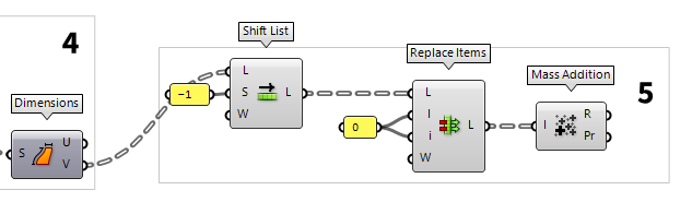
5
Find coordinates in x-direction
As stated, the coordinates for each slice on our base place depend on the
dimensions of the section curves. Here, we would like to have two rows of
section profiles, separated for each slicing direction. In x-direction we will
place the curves from the same set and their distance is given by the height of
each slice. The heights are obtained from output V of Dimensions
Dimensions (Dim)Inputs Surface (S) Surface to measure Outputs U dimension (U) Approximate dimension in U direction V dimension (V) Approximate dimension in V direction
The list of x-coordinates ought to start at 0, but currently starts with the
first height. Therefore, we use Shift List Shift List (Shift)
Inputs List (L) List to shift Shift (S) Shift offset Wrap (W) Wrap values Outputs List (L) Shifted list -1. Then we use Replace Items Replace Items (Replace)
Inputs List (L) List to modify Item (I) Items to replace with. If no items are supplied, nulls will be inserted. Indices (i) Replacement index for each item Wrap (W) If true, indices will be wrapped Outputs List (L) List with replaced values 0.
The component Mass Addition Mass Addition (MA)
Inputs Input (I) Input values for mass addition. Outputs Result (R) Result of mass addition Partial Results (Pr) List of partial results
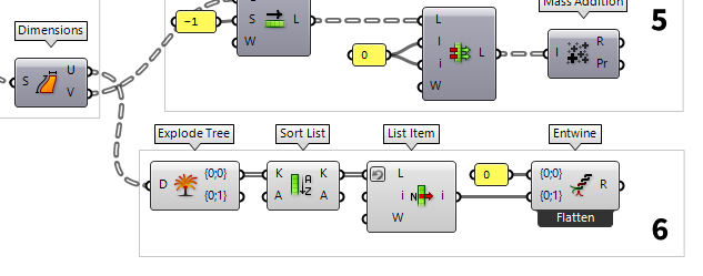
6
Find coordinates in y-direction
For the coordinates in y-direction, we will use a different approach, because
here we will just have two rows, one for each set of curves. The distance of the
rows is given by the largest width in the first set. The widths can be found at
output U of Dimensions
Dimensions (Dim)Inputs Surface (S) Surface to measure Outputs U dimension (U) Approximate dimension in U direction V dimension (V) Approximate dimension in V direction  Explode Tree (BANG!)
Inputs Data (D) Data to explode Outputs Branch 0 (-) All data inside the branch at index: 0 Branch 1 (-) All data inside the branch at index: 1
To find the largest width, we use Sort List Sort List (Sort)
Inputs Keys (K) List of sortable keys Values A (A) Optional list of values to sort synchronously Outputs Keys (K) Sorted keys Values A (A) Synchronous values in A  List Item (Item)
Inputs List (L) Base list Index (i) Item index Wrap (W) Wrap index to list bounds Outputs Item (i) Item at {i'} 0 and we use Entwine
Entwine (Entwine)Inputs Branch {0;0} ({0;0}) Data to entwine Branch {0;1} ({0;1}) Data to entwine Branch {0;2} ({0;2}) Data to entwine Outputs Result (R) Entwined result
7
Arrange slices in a plane
After calculating the coordinates for each slice, we arrange them all in a
single plane. To convert the coordinates to actual points, we will use Construct Point Construct Point (Pt)
Inputs X coordinate (X) {x} coordinate Y coordinate (Y) {y} coordinate Z coordinate (Z) {z} coordinate Outputs Point (Pt) Point coordinate
To place the section curves at their coordinates, we use Orient Orient (Orient)
Inputs Geometry (G) Base geometry Source (A) Initial plane Target (B) Final plane Outputs Geometry (G) Reoriented geometry Transform (X) Transformation data
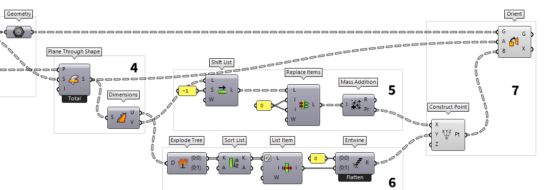

The result of this tutorial could now be plotted or fabricated with a CNC machine
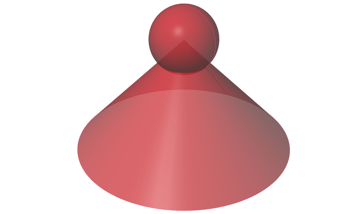
Test your skills
In the tutorial above, there was one geometric object to be sliced. Usually, we have more than one and now it’s your turn to tweak the algorithm so that it can handle several geometric objects. The section profiles on the base plane should contain all curves from one section. To keep it simple, let’s add a sphere to the tip of the cone.

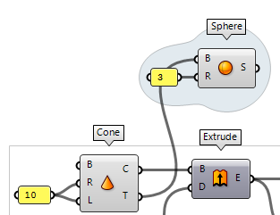
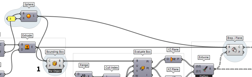
Connect the sphere
To include the sphere, we connect it
to input C of Bounding Box
Bounding Box (BBox)Inputs Content (C) Geometry to contain Plane (P) BoundingBox orientation plane Outputs Box (B) Aligned bounding box in world coordinates Box (B) Bounding box in orientation plane coordinates
Brep | Plane (Sec)Inputs Brep (B) Base Brep Plane (P) Section plane Outputs Curves (C) Section curves Points (P) Section points
Fix data structure
To change the data handling, we
right-click the component Bounding Box
Bounding Box (BBox)Inputs Content (C) Geometry to contain Plane (P) BoundingBox orientation plane Outputs Box (B) Aligned bounding box in world coordinates Box (B) Bounding box in orientation plane coordinates
Also, we have graft input P of Brep | Plane
Brep | Plane (Sec)Inputs Brep (B) Base Brep Plane (P) Section plane Outputs Curves (C) Section curves Points (P) Section points
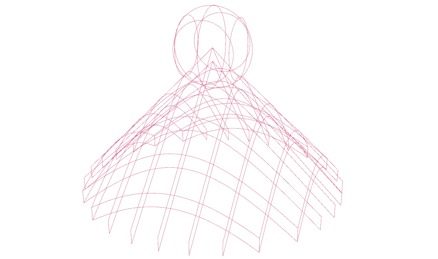
In the Rhino viewport, we can see that the arrangement on one layer is not yet
working as expected. This is caused by the changed data structure; Plane Through Shape
Plane Through Shape (PxS)Inputs Plane (P) Surface plane Shape (S) Shape to exceed Inflate (I) Boundary inflation amount Outputs Surface (S) Resulting planar surface

Capture the items in a single plane
The problem is that
Plane Through Shape
Plane Through Shape (PxS)Inputs Plane (P) Surface plane Shape (S) Shape to exceed Inflate (I) Boundary inflation amount Outputs Surface (S) Resulting planar surface
Brep | Plane (Sec)Inputs Brep (B) Base Brep Plane (P) Section plane Outputs Curves (C) Section curves Points (P) Section points
Trim Tree (Trim)Inputs Tree (T) Data tree to flatten Depth (D) Number of outermost branches to merge Outputs Tree (T) Trimmed data tree
The Plane Through Shape component has no option for this and we use another
Bounding Box
Bounding Box (BBox)Inputs Content (C) Geometry to contain Plane (P) BoundingBox orientation plane Outputs Box (B) Aligned bounding box in world coordinates Box (B) Bounding box in orientation plane coordinates
Trim Tree (Trim)Inputs Tree (T) Data tree to flatten Depth (D) Number of outermost branches to merge Outputs Tree (T) Trimmed data tree
Plane Through Shape (PxS)Inputs Plane (P) Surface plane Shape (S) Shape to exceed Inflate (I) Boundary inflation amount Outputs Surface (S) Resulting planar surface
As we can see, we still need to adjust Orient
Orient (Orient)Inputs Geometry (G) Base geometry Source (A) Initial plane Target (B) Final plane Outputs Geometry (G) Reoriented geometry Transform (X) Transformation data