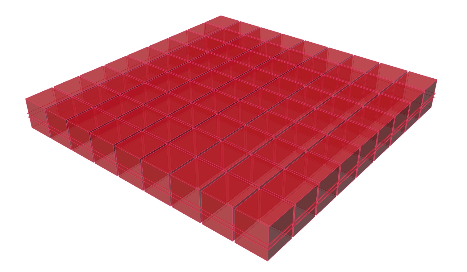
In this tutorial, we have a look at different functions that involve numeric domains. To illustrate this topic, we will create a tapered girder grid.

Grasshopper
1
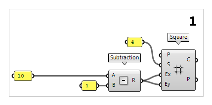
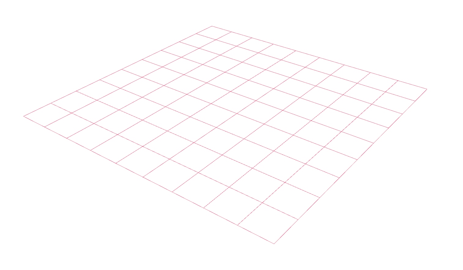
Create basic grid
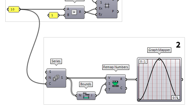
First thing we do, is to define the number of girders that we want to have in
each direction. This number is written in a Panel Panel
Panel10). The
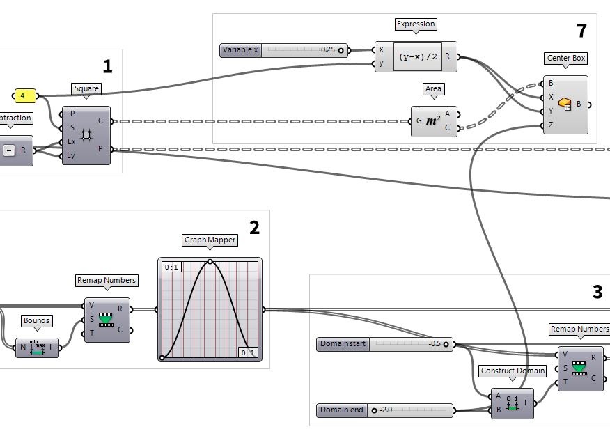
component Square Square (SqGrid)
Inputs Plane (P) Base plane for grid Size (S) Size of grid cells Extent X (Ex) Number of grid cells in base plane x direction Extent Y (Ey) Number of grid cells in base plane y direction Outputs Cells (C) Grid cell outlines Points (P) Points at grid corners 1 from our number of
girders. For this, we use a Subtraction Subtraction (A-B)
Inputs A (A) First operand for subtraction B (B) Second operand for subtraction Outputs Result (R) Result of subtraction
2
Set curves for the sag
The tapering of the girders will not be same for each individual girder, but instead the network of girders should correspond to a sagging surface. The sag or the form of the surface will follow a sine curve in every cross-section. This will be controlled by offsetting every node of the grid and thus defining the bottom chord of the girders.

Each girder is segmented by the girders running in the perpendicular direction
and we need the vertical coordinate according to the sine curve for each
intersection. To do this, we need an array that has the same length as the
number of girders in one direction. This is achieved with a Series Series (Series)
Inputs Start (S) First number in the series Step (N) Step size for each successive number Count (C) Number of values in the series Outputs Series (S) Series of numbers
A sine curve can be drawn with the Graph Mapper Graph Mapper (Graph)
The default range of the Graph Mapper’s coordinates is from 0 to 1 on each axis and it’s advised to leave it like that and rather apply a factor to the output to scale to the desired magnitude. And of course, if we alter the internal coordinates, we also have to provide input data in this range.
The output of our Series is not within the needed range and we use Remap Numbers Remap Numbers (ReMap)
Inputs Value (V) Value to remap Source (S) Source domain Target (T) Target domain Outputs Mapped (R) Remapped number Clipped (C) Remapped and clipped number  Bounds (Bnd)
Inputs Numbers (N) Numbers to include in Bounds Outputs Domain (I) Numeric Domain between the lowest and highest numbers in {N} 0 To 1. The values to be remapped are set
at input V and to which we connect our Series. The remapped series are now
the input (x-values) for the Graph Mapper.
3
Get sag values for the surface
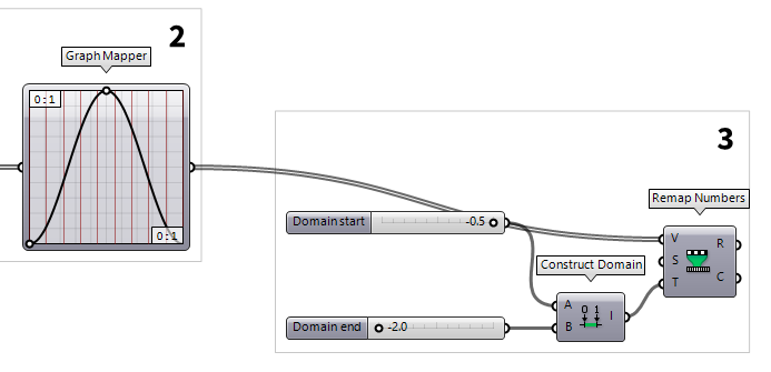
The output (y-values) of the Graph Mapper
Graph Mapper (Graph)0 To 1 and we need to remap the values to the desired magnitude
before they define the bottom chord of our girders. Thus, we us Remap Numbers
Remap Numbers (ReMap)Inputs Value (V) Value to remap Source (S) Source domain Target (T) Target domain Outputs Mapped (R) Remapped number Clipped (C) Remapped and clipped number 0 To 1 is
correct and we need a target domain.
To define the target domain we use Construct Domain Construct Domain (Dom)
Inputs Domain start (A) Start value of numeric domain Domain end (B) End value of numeric domain Outputs Domain (I) Numeric domain between {A} and {B}  Number Slider
-2.0..-0.5 into the canvas search.
4
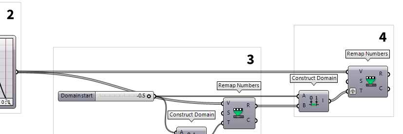
Get tapering values for all points
So far, we have obtained values for the sag of the surface, or more precisely, for the cross-section in the middle. When describing this surface with a grid of tapered girders, the girders towards the edges must be less tapered than the ones in the middle. Therefore, each girder needs to have the same height at the edge of the surface, but a different height in its respective middle.

To implement this, we use another Construct Domain
Construct Domain (Dom)Inputs Domain start (A) Start value of numeric domain Domain end (B) End value of numeric domain Outputs Domain (I) Numeric domain between {A} and {B}
These domains will now become the target domain T of another Remap Numbers
Remap Numbers (ReMap)Inputs Value (V) Value to remap Source (S) Source domain Target (T) Target domain Outputs Mapped (R) Remapped number Clipped (C) Remapped and clipped number
5
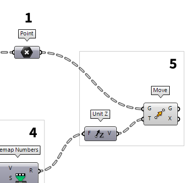
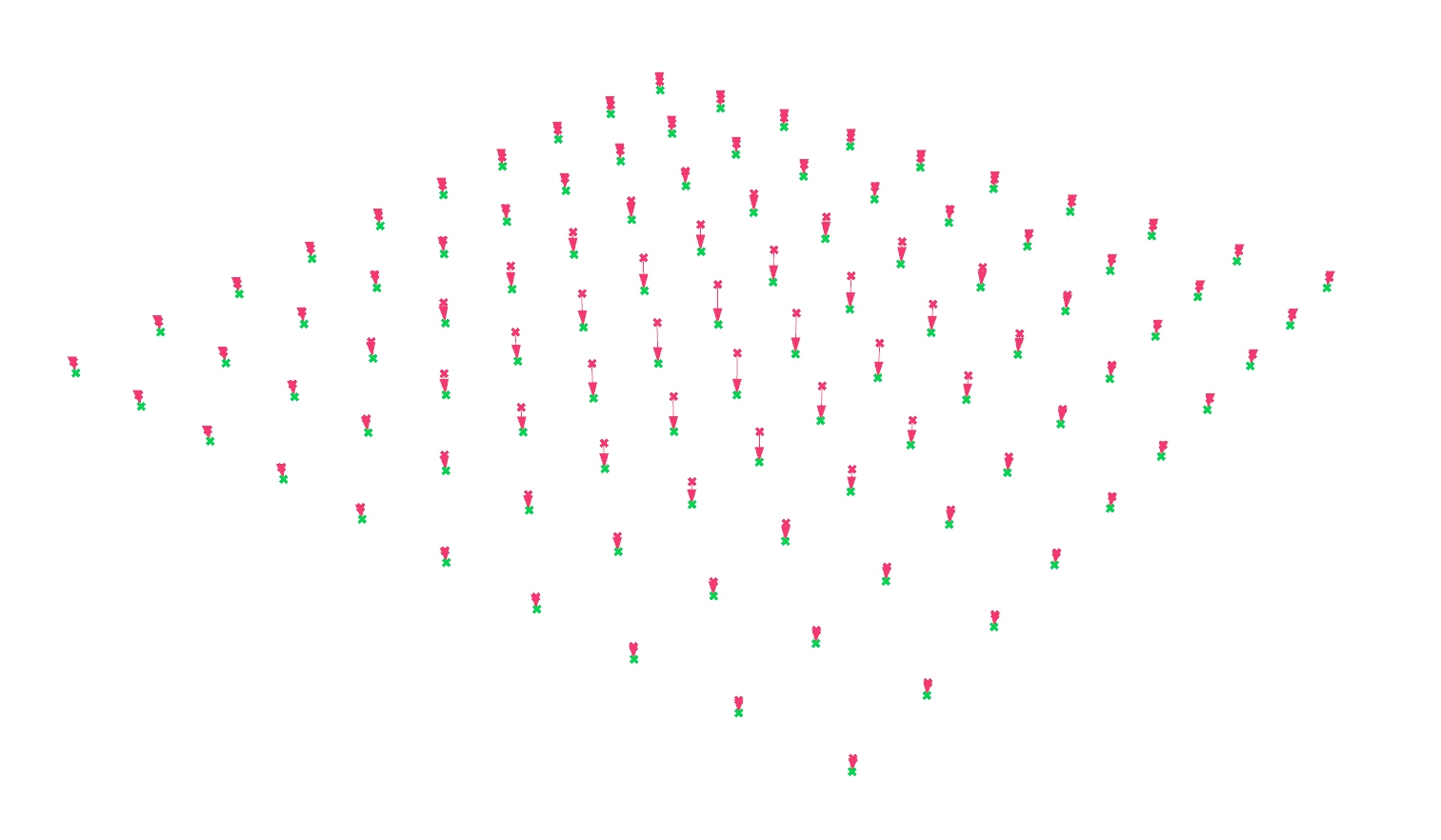
Move points accordingly
After generating the heights, we will connect them to a Unit Z Unit Z (Z)
Inputs Factor (F) Unit multiplication Outputs Unit vector (V) World {z} vector  Move (Move)
Inputs Geometry (G) Base geometry Motion (T) Translation vector Outputs Geometry (G) Translated geometry Transform (X) Transformation data
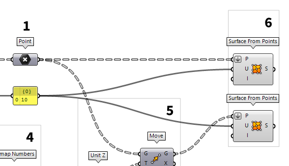
6
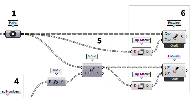
Arrange points in rows and columns
The grid points are organized in rows, but we also need the points in the column
direction. To get them, we connect a Flip Matrix Flip Matrix (Flip)
Inputs Data (D) Data matrix to flip Outputs Data (D) Flipped data matrix  Entwine (Entwine)
Inputs Branch {0;0} ({0;0}) Data to entwine Branch {0;1} ({0;1}) Data to entwine Branch {0;2} ({0;2}) Data to entwine Outputs Result (R) Entwined result
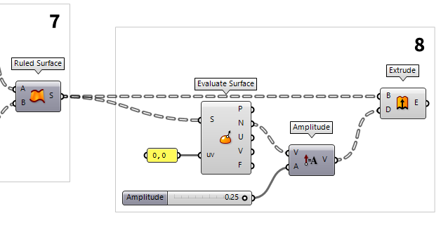
7
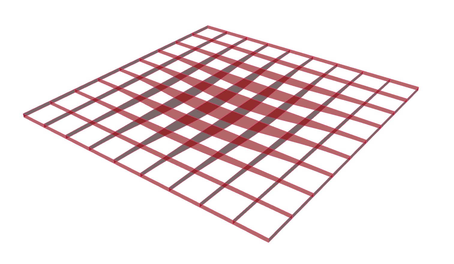
Generate outlines and surfaces
Now, that we have all needed points and did the sorting, we connect a PolyLine PolyLine (PLine)
Inputs Vertices (V) Polyline vertex points Closed (C) Close polyline Outputs Polyline (Pl) Resulting polyline  Interpolate (IntCrv)
Inputs Vertices (V) Interpolation points Degree (D) Curve degree Periodic (P) Periodic curve KnotStyle (K) Knot spacing (0=uniform, 1=chord, 2=sqrtchord) Outputs Curve (C) Resulting nurbs curve Length (L) Curve length Domain (D) Curve domain  Ruled Surface (RuleSrf)
Inputs Curve A (A) First curve Curve B (B) Second curve Outputs Surface (S) Ruled surface between A and B

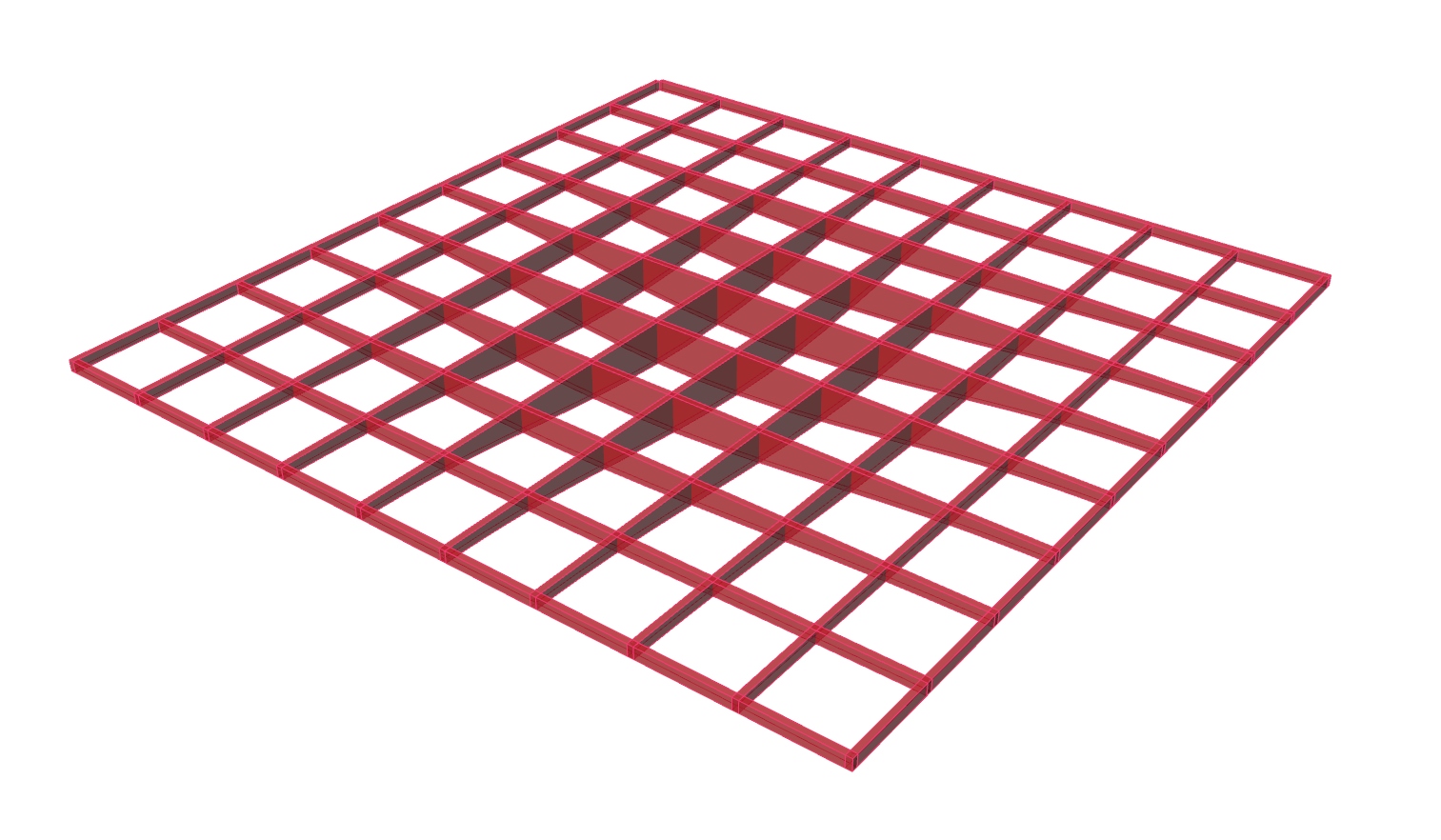
8
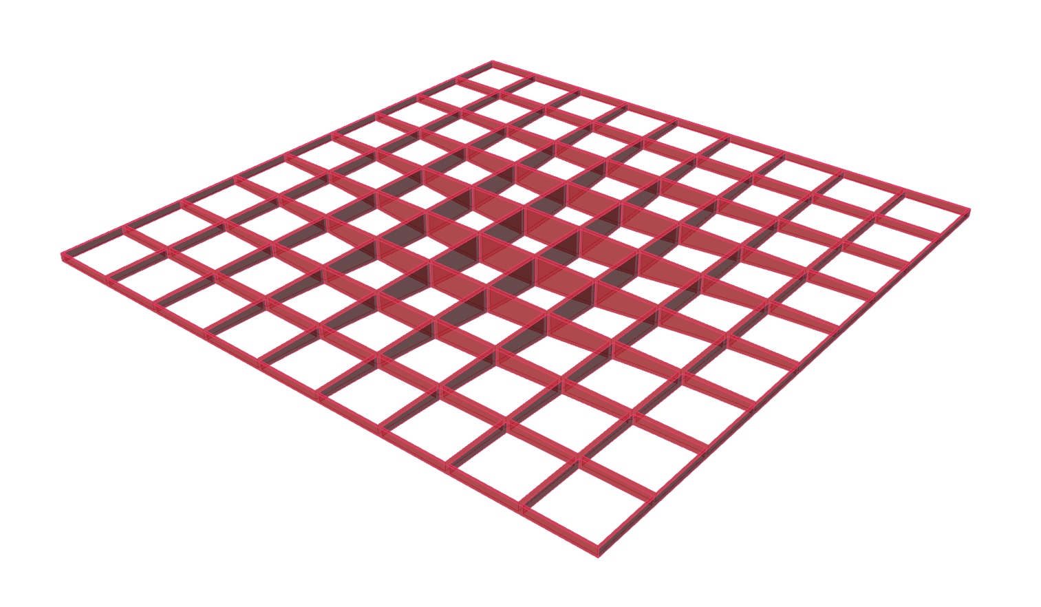
Create tapered volumes as girders
The last step of this tutorial is to turn the surfaces into volumes. This is
done with an Extrude Extrude (Extr)
Inputs Base (B) Profile curve or surface Direction (D) Extrusion direction Outputs Extrusion (E) Extrusion result  Evaluate Surface (EvalSrf)
Inputs Surface (S) Base surface Point (uv) {uv} coordinate to evaluate Outputs Point (P) Point at {uv} Normal (N) Normal at {uv} U direction (U) U direction at {uv} V direction (V) V direction at {uv} Frame (F) Frame at {uv} 0,0 as uv-values, but any value pair will work, because we have planar
surfaces.
The normals are outputted at N and we append an Amplitude Amplitude (Amp)
Inputs Vector (V) Base vector Amplitude (A) Amplitude (length) value Outputs Vector (V) Resulting vector
Number Slider
Test your skills
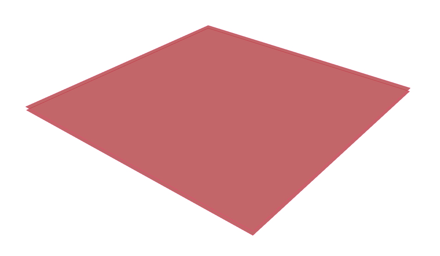
The solution above works fine, but it doesn’t give us the smoothest results, because the beams intersect. To get nicer results and also to let the bottoms align with the sagging surface at the intersections, we can create the sagging surface first and then cut the girders out. Thus, instead of the beams, we need a surface for the top and a second one for the button. Also, we need some boxes to trim holes into the surfaces. Enough said, now it’s your turn to try this approach yourself.
Create two surfaces
From the solution above, we can keep
everything until after step 5. But, instead of creating curves for the girders,
we create surfaces from the grid of points. The component Surface From Points Surface From Points (SrfGrid)
Inputs Points (P) Grid of points U Count (U) Number of points in {u} direction Interpolate (I) Interpolate samples Outputs Surface (S) Resulting surface
Create cutting boxes
We create a box in each cell that
will serve as trimming objects for the surfaces. We start with defining the
boxes right after step 1, where we got the grid cell outlines from output C
of the Square component. The center of each cell is then generated with an Area Area (Area)
Inputs Geometry (G) Brep, mesh or planar closed curve for area computation Outputs Area (A) Area of geometry Centroid (C) Area centroid of geometry  Center Box (Box)
Inputs Base (B) Base plane X (X) Size of box in {x} direction. Y (Y) Size of box in {y} direction. Z (Z) Size of box in {z} direction. Outputs Box (B) Resulting box
The height of the boxes should not be smaller than the tallest girder. This
value was defined by the Number Slider of the Domain end in step 2 and we
can grab it from there. The expansion of the boxes in x- and y-direction should
be half of each cell size minus half of the girder width. To calculate this, we
use an Expression Expression (Expression)
Inputs Variable x (x) Expression variable Variable y (y) Expression variable Outputs Result (R) Result of expression (y-x)/2. At
input x we connect a Number Slider
Number Slider
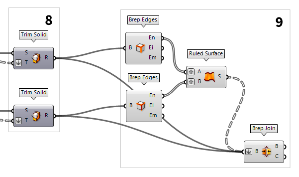
Trim surfaces
To cut holes into the surfaces, we use the
component Trim Solid Trim Solid (Trim)
Inputs Shape (S) Shape to trim Cutters (T) Trimming shapes Outputs Result (R) Shape with holes
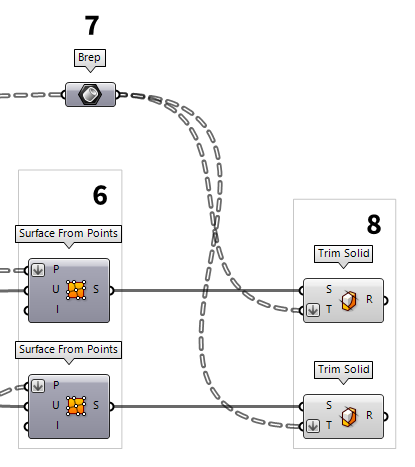

Create missing surfaces
To close the missing sides, we
create surfaces between the edges of the top and bottom surface. These edges can
be extracted with the Brep Edges Brep Edges (Edges)
Inputs Brep (B) Base Brep Outputs Naked (En) Naked edge curves Interior (Ei) Interior edge curves Non-Manifold (Em) Non-Manifold edge curves
Ruled Surface (RuleSrf)Inputs Curve A (A) First curve Curve B (B) Second curve Outputs Surface (S) Ruled surface between A and B  Brep Join (Join)
Inputs Breps (B) Breps to join Outputs Breps (B) Joined Breps Closed (C) Closed flag for each resulting Brep