In general, it’s advised to generate meshes as late as possible in the algorithm
because when we convert surfaces to meshes we lose topographic information
Trim a mesh with another one
For this method, we look at random meshes and then trim one with the other. In the following, we have a sphere that is interpenetrated with a cylinder and the part of the sphere that is inside the cylinder will be cropped. Then, the created cutout is closed with a planar cap.
The component Mesh Sphere Mesh Sphere (MSphere)
Inputs Base (B) Base plane Radius (R) Radius of mesh sphere U Count (U) Number of faces around sphere V Count (V) Number of faces from pole to pole Outputs Mesh (M) Mesh sphere  Cylinder (Cyl)
Inputs Base (B) Base plane Radius (R) Cylinder radius Length (L) Cylinder height Outputs Cylinder (C) Resulting cylinder  Mesh Brep (Mesh)
Inputs Brep (B) Brep geometry Settings (S) Settings to be used by meshing algorithm Outputs Mesh (M) Mesh approximation
The component Mesh Split Mesh Split (MSplit)
Inputs Mesh (M) Mesh to split Splitters (S) Meshes to split with Outputs Result (R) Result of mesh split  List Item (Item)
Inputs List (L) Base list Index (i) Item index Wrap (W) Wrap index to list bounds Outputs Item (i) Item at {i'} 0 of the
index i is what we are looking for. Otherwise, we have to change the index or
set up some components to calculate the index of the desired surface (it’s
often the one with the largest area). We have now performed the trimming
operation.
To close the remaining openings with another mesh, we first have to get the
edges of the holes with Mesh Edges Mesh Edges (MEdges)
Inputs Mesh (M) Mesh for edge extraction Outputs Naked Edges (E1) Edges with valence 1 (a single adjacent face) Interior Edges (E2) Edges with valence 2 (two adjacent faces) Non-Manifold Edges (E3) Edges with valence 3 or higher  Join Curves (Join)
Inputs Curves (C) Curves to join Preserve (P) Preserve direction of input curves Outputs Curves (C) Joined curves and individual curves that could not be joined.  Discontinuity (Disc)
Inputs Curve (C) Curve to analyze Level (L) Level of discontinuity to test for (1=C1, 2=C2, 3=Cinfinite) Outputs Points (P) Points at discontinuities Parameters (t) Curve parameters at discontinuities  Planar (Planar)
Inputs Curve (C) Curve to evaluate Outputs Planar (p) Planarity of curve Plane (P) Curve plane Deviation (D) Deviation from curve plane  Delaunay Mesh (Del)
Inputs Points (P) Points for triangulate Plane (Pl) Optional base plane. If no plane is provided, then the best-fit plane will be used. Outputs Mesh (M) Mesh
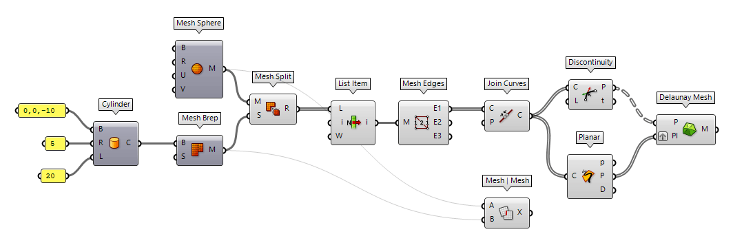
As an alternative, we can also use the component Mesh | Mesh Mesh | Mesh (MMX)
Inputs Mesh A (A) First mesh Mesh B (B) Second mesh Outputs Intersections (X) Intersection polylines
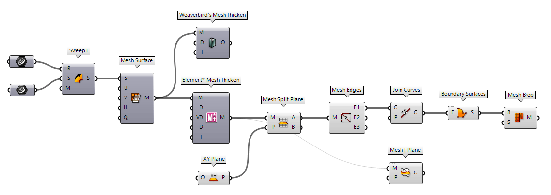
Trim a mesh with a plane
Another possibility to split a mesh is with a plane. Let’s assume is any mesh with an assigned thickness. This can be quickly done with the Grasshopper plugins Weaverbird or Element* and is a common scenario for 3D printing.
Now, we use Mesh Split Plane Mesh Split Plane (MSplit)
Inputs Mesh (M) Mesh to split Plane (P) Splitting plane Outputs Above (A) Pieces above the plane. Below (B) Pieces below the plane.
Mesh Edges (MEdges)Inputs Mesh (M) Mesh for edge extraction Outputs Naked Edges (E1) Edges with valence 1 (a single adjacent face) Interior Edges (E2) Edges with valence 2 (two adjacent faces) Non-Manifold Edges (E3) Edges with valence 3 or higher
Join Curves (Join)Inputs Curves (C) Curves to join Preserve (P) Preserve direction of input curves Outputs Curves (C) Joined curves and individual curves that could not be joined.  Mesh | Plane (Sec)
Inputs Mesh (M) Base Mesh Plane (P) Section plane Outputs Curves (C) Section polylines
Unlike before, the intersection curve in this example has inflection points and
the opening is concave. Thus, the Delaunay algorithm will not generate the
desired mesh. We have to take a little detour by generating a Boundary Surfaces Boundary Surfaces (Boundary)
Inputs Edges (E) Boundary curves Outputs Surfaces (S) Resulting boundary surfaces
Mesh Brep (Mesh)Inputs Brep (B) Brep geometry Settings (S) Settings to be used by meshing algorithm Outputs Mesh (M) Mesh approximation
Particularities of non-planar openings
In the examples above, the intersection
curves were planar, which is
not always true. For example, if two cylinders intersect, we get a twisted
intersection curve. In case of meshed cylinders, this intersection curve is a
polyline and there is no distinct method to cap the opening. We then have to
think of an appropriate way that suits our design. In Grasshopper, Fragment Patch Fragment Patch (FPatch)
Inputs Boundary (B) Fragment polyline boundary Outputs Patch (P) Fragmented patch
For these twisted intersection curves, it’s easier to keep the solids as
surfaces and solve there intersection. We can then use Patch Patch (Patch)
Inputs Curves (C) Curves to patch Points (P) Points to patch Spans (S) Number of spans Flexibility (F) Patch flexibility (low number; less flexibility) Trim (T) Attempt to trim the result Outputs Patch (P) Patch result
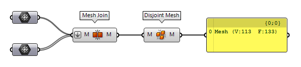
To check, whether the generated caps close the openings and everything forms is
a tight union, we can combine the individual meshes with Mesh Join Mesh Join (MJoin)
Inputs Meshes (M) Meshes to join Outputs Mesh (M) Mesh join result  Disjoint Mesh (Disjoint)
Inputs Mesh (M) Mesh to split Outputs Meshes (M) Disjoint pieces
Particularities of other regular openings
The methods described above will not always be satisfying in some corner cases. For example if we need a mesh suitable for FEM calculations or have an intersection polyline that doesn’t deflect at every vertex. To solve these issues, we have to make sure that every vertex is part of the mesh or that additional faces are creating within the region of the opening.
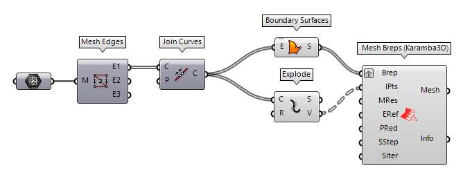
To solve the above, we can use Mesh Edges
Mesh Edges (MEdges)Inputs Mesh (M) Mesh for edge extraction Outputs Naked Edges (E1) Edges with valence 1 (a single adjacent face) Interior Edges (E2) Edges with valence 2 (two adjacent faces) Non-Manifold Edges (E3) Edges with valence 3 or higher
Join Curves (Join)Inputs Curves (C) Curves to join Preserve (P) Preserve direction of input curves Outputs Curves (C) Joined curves and individual curves that could not be joined.
Boundary Surfaces (Boundary)Inputs Edges (E) Boundary curves Outputs Surfaces (S) Resulting boundary surfaces  Explode (Explode)
Inputs Curve (C) Curve to explode Recursive (R) Recursive decomposition until all segments are atomic Outputs Segments (S) Exploded segments that make up the base curve Vertices (V) Vertices of the exploded segments  Mesh Breps (Karamba3D) (Mesh Breps)
Inputs Brep (Brep) Breps or surfaces to mesh Inclusion Points (IPts) Points to include into the mesh Mesh Resolution (MRes) Target mesh size [m] Edge Refinement Factor (ERef) Resolution refinement at Brep edges. Point Reduction (PRed) Optional reduction of points at narrowing UV-spaces. Disabling point reduction results in a much faster output but mesh vertices may have a greater difference of density Smoothing Step Size (SStep) Smoothing step size for each iteration ('0' means no smoothing)
Note that mesh smoothing can result self-overlapping meshes at inclusion points!Smoothing Iterations (SIter) Smoothing iterations ('0' means no smoothing)
Note that mesh smoothing can result self-overlapping meshes at inclusion points!Outputs Mesh (Mesh) Output Mesh Info (Info) Output stats