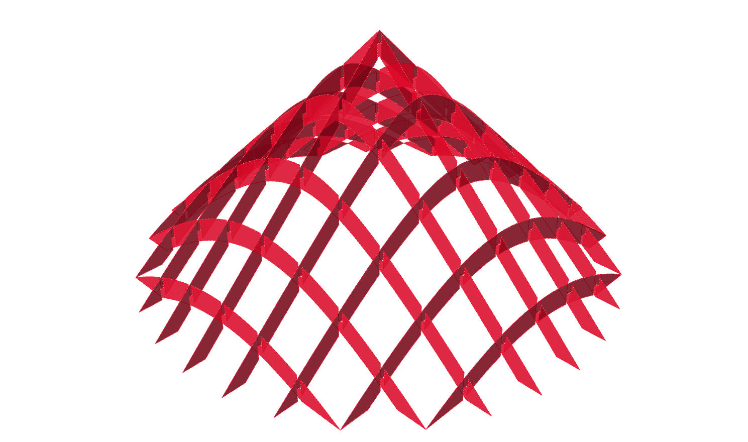
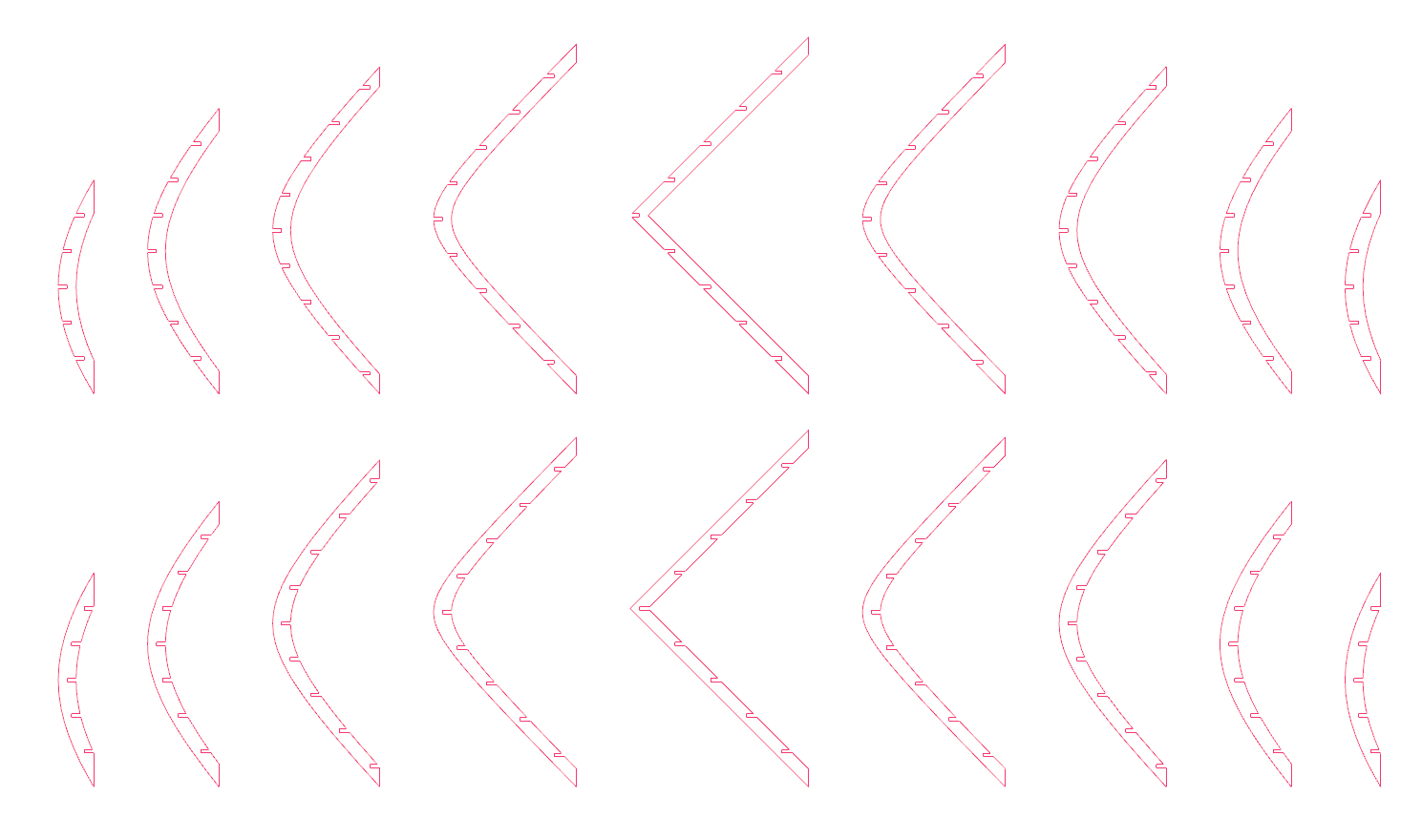
This tutorial builds upon the result from Generate slices from a 3d model in which we
created a sliced solid and arranged those slices in one flat layer. To generate
a sliceform, we have to create slots for the opposed slices to interlock. It’s
assumed that the slices meet at right angles. The result could be fabricated
with a CNC machine
Grasshopper
1
Define initial geometric object
To start, we open the result from the tutorial Generate slices from a 3d model and
look for the section curves, which are located at the end of step 3 in the Geometry Geometry (Geo)
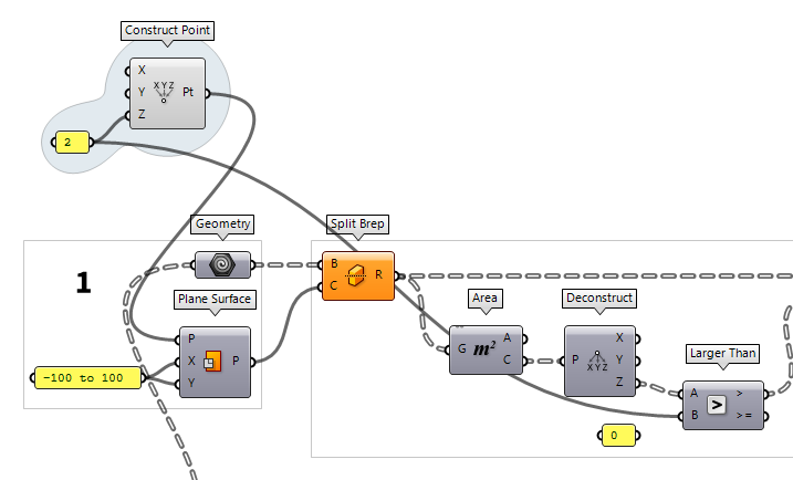
Our fabricated model should stand without wobbling and therefore we will trim
everything underneath a ground plane. This creates a proper bearing area. We
create the ground surface with the component Plane Surface Plane Surface (PlaneSrf)
Inputs Plane (P) Surface base plane X Size (X) Dimensions in X direction Y Size (Y) Dimensions in Y direction Outputs Plane (P) Resulting plane surface -100 To 100 as dimensions for each direction.

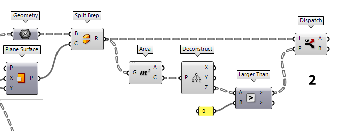
2
Trim slices with ground surface
The component Split Brep Split Brep (Split)
Inputs Brep (B) Brep to split Cutter (C) Cutting shape Outputs Result (R) Brep fragments
To compute the center points, we use Area Area (Area)
Inputs Geometry (G) Brep, mesh or planar closed curve for area computation Outputs Area (A) Area of geometry Centroid (C) Area centroid of geometry  Deconstruct (pDecon)
Inputs Point (P) Input point Outputs X component (X) Point {x} component Y component (Y) Point {y} component Z component (Z) Point {z} component  Larger Than (Larger)
Inputs First Number (A) Number to test Second Number (B) Number to test against Outputs Larger than (>) True if A > B … or Equal to (>=) True if A >= B 0 (assuming that the
ground plane is has no altitude). Dispatch Dispatch (Dispatch)
Inputs List (L) List to filter Dispatch pattern (P) Dispatch pattern Outputs List A (A) Dispatch target for True values List B (B) Dispatch target for False values

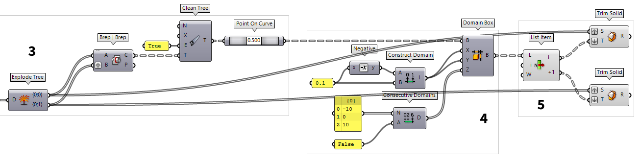
3
Find position of slots in the section surfaces
To create a sliceform, we must calculate where the slices meet. For this, we
need two lists; each direction of slices in one. After step 2, each section
surface has its own branch and we use Trim Tree Trim Tree (Trim)
Inputs Tree (T) Data tree to flatten Depth (D) Number of outermost branches to merge Outputs Tree (T) Trimmed data tree  Explode Tree (BANG!)
Inputs Data (D) Data to explode Outputs Branch 0 (-) All data inside the branch at index: 0 Branch 1 (-) All data inside the branch at index: 1
To solve the intersection for the slices, we use Brep | Brep Brep | Brep (BBX)
Inputs Brep A (A) First Brep Brep B (B) Second Brep Outputs Curves (C) Intersection curves Points (P) Intersection points  Clean Tree (Clean)
Inputs Remove Nulls (N) Remove null items from the tree. Remove Invalid (X) Remove invalid items from the tree. Remove Empty (E) Remove empty branches from the tree. Tree (T) Data tree to clean Outputs Tree (T) Spotless data tree
To to find a point on the line that was generated by the intersection, we use
Point On Curve Point On Curve (CurvePoint)

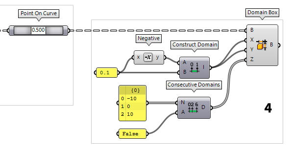
4
Create trimming objects for the slots
After finding the position of the slots, we need to set their dimensions. For
this, we use a Domain Box Domain Box (Box)
Inputs Base (B) Base plane X (X) Domain of the box in the {x} direction. Y (Y) Domain of the box in the {y} direction. Z (Z) Domain of the box in the {z} direction. Outputs Box (B) Resulting box 0.1 in each direction. To create a domain
from -0.1 to 0.1, we also need to get the Negative Negative (Neg)
Inputs Value (x) Input value Outputs Result (y) Output value  Construct Domain (Dom)
Inputs Domain start (A) Start value of numeric domain Domain end (B) End value of numeric domain Outputs Domain (I) Numeric domain between {A} and {B}
Domain Box (Box)Inputs Base (B) Base plane X (X) Domain of the box in the {x} direction. Y (Y) Domain of the box in the {y} direction. Z (Z) Domain of the box in the {z} direction. Outputs Box (B) Resulting box
When setting the height of the Domain Box, we have to make sure that it
reaches from the contact point of the opposed slots to the edge of the material.
Also, we need one box oriented in positive z-direction and one in negative. For
this, we use Consecutive Domains Consecutive Domains (Consec)
Inputs Numbers (N) Numbers for consecutive domains Additive (A) If True, values are added to a sum-total Outputs Domains (D) Domains describing the spaces between the numbers False to input A,
which will deactivate the values being added to a sum-total. To define the
heights, we use a Panel Panel
Panel-10, 0 and 10 and connect it to input A. The resulting Domains
are then connected to the Domain Box as input Z.
5
Cut slots for interlocking
When cutting the slots for the slices to interlock, we need one slot to face
upward and the other to face downward. To select the boxes in once direction,
we append a List Item List Item (Item)
Inputs List (L) Base list Index (i) Item index Wrap (W) Wrap index to list bounds Outputs Item (i) Item at {i'}
Domain Box (Box)Inputs Base (B) Base plane X (X) Domain of the box in the {x} direction. Y (Y) Domain of the box in the {y} direction. Z (Z) Domain of the box in the {z} direction. Outputs Box (B) Resulting box
To cut the slots into the slices, we use Trim Solid Trim Solid (Trim)
Inputs Shape (S) Shape to trim Cutters (T) Trimming shapes Outputs Result (R) Shape with holes
Trim Solid (Trim)Inputs Shape (S) Shape to trim Cutters (T) Trimming shapes Outputs Result (R) Shape with holes
6
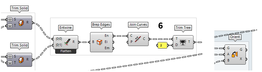
Create a seamless edge for each slice
After creating the slots in the slices, we will inject them into the algorithm
from Generate slices from a 3d model to arrange the slices on a single plane for
fabrication. Unlike in that tutorial, we now have independent lists and surfaces
instead of outline curves. To fix the first, we use Entwine Entwine (Entwine)
Inputs Branch {0;0} ({0;0}) Data to entwine Branch {0;1} ({0;1}) Data to entwine Branch {0;2} ({0;2}) Data to entwine Outputs Result (R) Entwined result
To convert the surfaces into curves, we attach a Brep Edges Brep Edges (Edges)
Inputs Brep (B) Base Brep Outputs Naked (En) Naked edge curves Interior (Ei) Interior edge curves Non-Manifold (Em) Non-Manifold edge curves  Join Curves (Join)
Inputs Curves (C) Curves to join Preserve (P) Preserve direction of input curves Outputs Curves (C) Joined curves and individual curves that could not be joined.
Trim Tree (Trim)Inputs Tree (T) Data tree to flatten Depth (D) Number of outermost branches to merge Outputs Tree (T) Trimmed data tree 2 levels.
We can then connect the resulting data tree to the Geometry
Geometry (Geo) Orient (Orient)
Inputs Geometry (G) Base geometry Source (A) Initial plane Target (B) Final plane Outputs Geometry (G) Reoriented geometry Transform (X) Transformation data
Test your skills
In the instructions above, the ground plane was at z = 0. Now it’s your turn
to alter the algorithm in a way that we can set the altitude of the trimming
plane as a variable parameter.
Set a parameter for the horizontal plane
The modifications that need to be made to cut the object require little effort:
First we use Construct Point Construct Point (Pt)
Inputs X coordinate (X) {x} coordinate Y coordinate (Y) {y} coordinate Z coordinate (Z) {z} coordinate Outputs Point (Pt) Point coordinate
Larger Than (Larger)Inputs First Number (A) Number to test Second Number (B) Number to test against Outputs Larger than (>) True if A > B … or Equal to (>=) True if A >= B
After this modification the Split Brep
Split Brep (Split)Inputs Brep (B) Brep to split Cutter (C) Cutting shape Outputs Result (R) Brep fragments
In this example, the variation of the cutting plane results in fewer slices. The
old algorithm that we want to plug into does not account for that yet.
Therefore, we have to remove the now redundant planes from the Plane Through Shape Plane Through Shape (PxS)
Inputs Plane (P) Surface plane Shape (S) Shape to exceed Inflate (I) Boundary inflation amount Outputs Surface (S) Resulting planar surface
Remove redundant planes
When we compare the output from step 2 of this tutorial with the initial
algorithm, we can see that trimming the cone sections with the elevated plane
results in fewer slices. Now, we need to reduce redundant planes and the best
place to start is at the output of the Entwine
Entwine (Entwine)Inputs Branch {0;0} ({0;0}) Data to entwine Branch {0;1} ({0;1}) Data to entwine Branch {0;2} ({0;2}) Data to entwine Outputs Result (R) Entwined result  Graft Tree (Graft)
Inputs Tree (T) Data tree to graft Outputs Tree (T) Grafted data tree  Tree Statistics (TStat)
Inputs Tree (T) Data Tree to analyze Outputs Paths (P) All the paths of the tree Length (L) The length of each branch in the tree Count (C) Number of paths and branches in the tree
The Dispatch
Dispatch (Dispatch)Inputs List (L) List to filter Dispatch pattern (P) Dispatch pattern Outputs List A (A) Dispatch target for True values List B (B) Dispatch target for False values  Null Item (Null)
Inputs Item (I) Item to test Outputs Null Flags (N) True if item is Null Invalid Flags (X) True if item is Invalid Description (D) A textual description of the object state
Dispatch (Dispatch)Inputs List (L) List to filter Dispatch pattern (P) Dispatch pattern Outputs List A (A) Dispatch target for True values List B (B) Dispatch target for False values
At output A of Dispatch we find the names of the branches that are empty
and we connect this to an input M of a Split Tree Split Tree (Split)
Inputs Data (D) Tree to split Masks (M) Splitting masks Outputs Positive (P) Positive set of data (all branches that match any of the masks) Negative (N) Negative set of data (all branches that do not match any of the masks
Trim Tree (Trim)Inputs Tree (T) Data tree to flatten Depth (D) Number of outermost branches to merge Outputs Tree (T) Trimmed data tree
The last part is to take a Plane Through Shape
Plane Through Shape (PxS)Inputs Plane (P) Surface plane Shape (S) Shape to exceed Inflate (I) Boundary inflation amount Outputs Surface (S) Resulting planar surface
