3D printing follows the ideas of rapid prototyping
The purpose of crafting a model with the techniques of rapid prototyping is evaluation and decision-making. For this, the model doesn’t need to have all the details, but should provide sufficient insight into the sought specifications. Before prototyping a copy of our design, we should think about the level of abstraction. Sometimes it’s easier to create a simplified version just for printing purposes.
We have to keep in mind, that 3D printing has its own limitations of what can be printed. Especially with printers that use fused filament fabrication, in which material is deposited layer by layer. Levitating and strongly inclined areas are only possible with support structure. For lattice structures, this support would interfere with other elements of our design and thus it can be difficult to achieve the desired results. If we have a discretized structure that will have some sort of covering later on, it might be easier to print the surface belonging to the covering as well and to offset the structural elements to make their pattern visible.
The size of the fabricated model is limited by the size of the printer, which usually have a build volume of 200 to 300 mm in each direction. Though the actual fabrication process and material may vary, most printers are limited to one material and one color at a time. This tutorial is written with these assumptions in mind.
Everything that ought to be printed has to have a volume. The first step in preparation for printing is to turn lines into pipes and give surfaces a thickness. Your 3D printer most commonly asks you to provide the data in a *.stl or *.3mf file format, which means that at some point the model also has to be converted into a mesh. This mesh has to be without any gaps and volumes should also not intersect each other. If we image that our model is getting filled with water, the water should not leak, but reach every part of the model. Even though printing software is getting smarter and may fix some shortcoming, it’s recommended to provide the best source material possible.
Instead of complex operations on meshes, like trimming the model at intersections by hand, or solving cases when a surface meets a mesh, it’s easier to convert everything into a volumetric model first and then into a mesh. A volumetric model consists of thousands independent tiny volumes, called voxels. You can think of them as blocks in a Minecraft map, in which a huge number of those little blocks make up the whole landscape. Once everything exists in voxel data, we can merge the individual voxeled objects into a combined cloud of voxels and then wrap a mesh around the voxel landscape.
To operate with voxels we need an extra plugin for Grasshopper. In this case, we will use Dendro. But other plugins that use the voxel approach should do the job just as fine.
Grasshopper
In Grasshopper, dimensions that we assign to objects are without any unit. Whenever we push something to Rhino, the geometry is baked in the unit of the opened document. In 3D printing, the most hassle-free procedure is to draw everything in millimeter. You can change the unit of a Rhino document in the status bar.
0
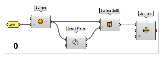
Create some source objects
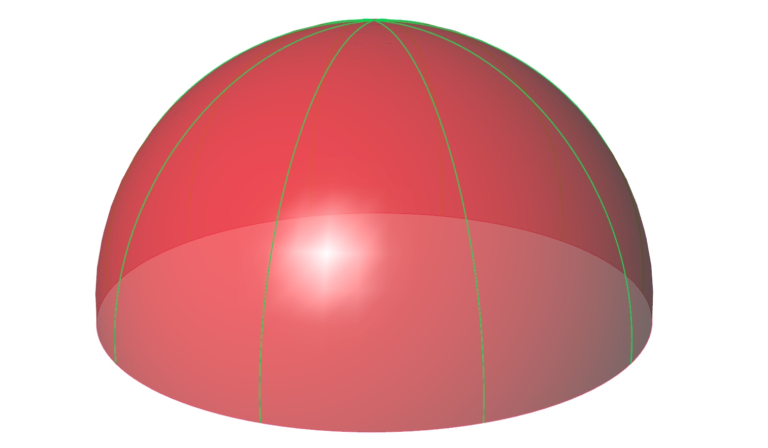
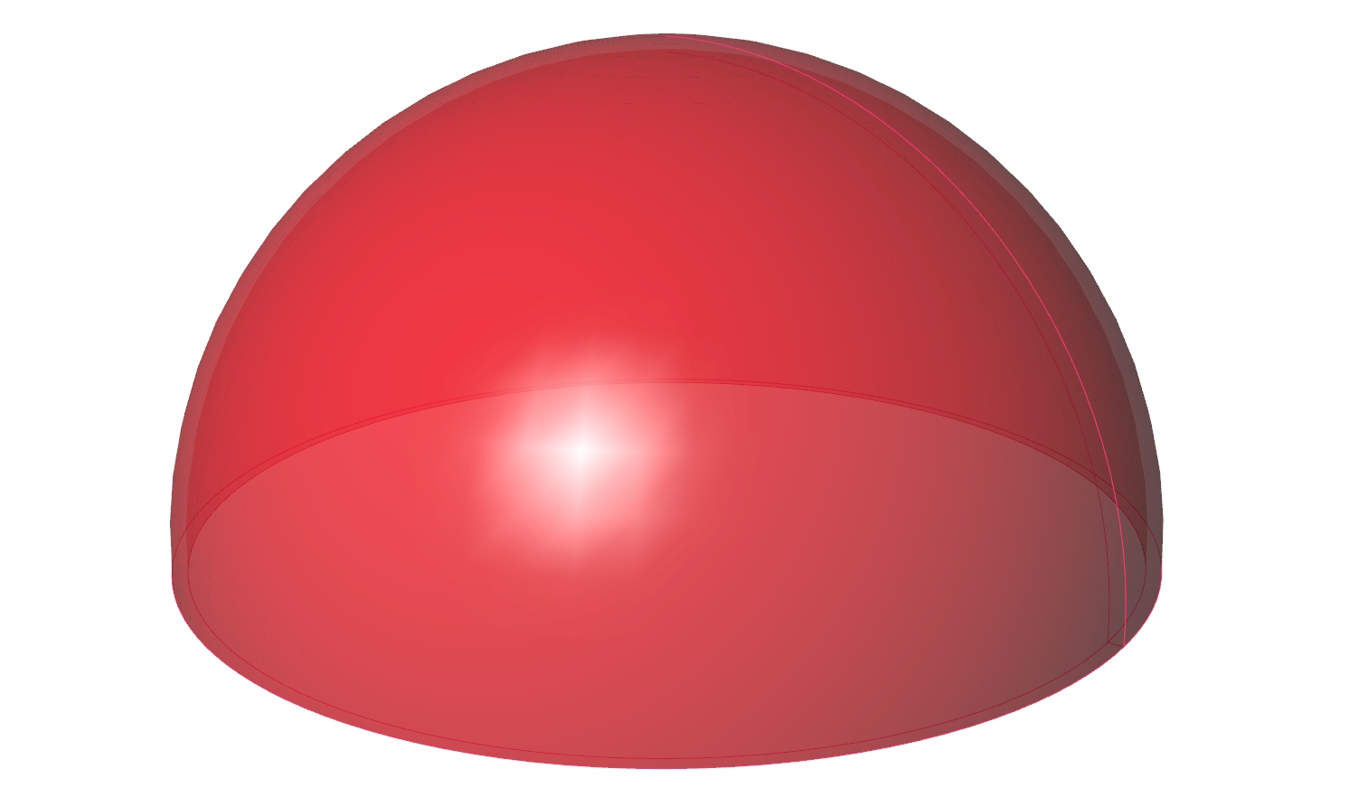
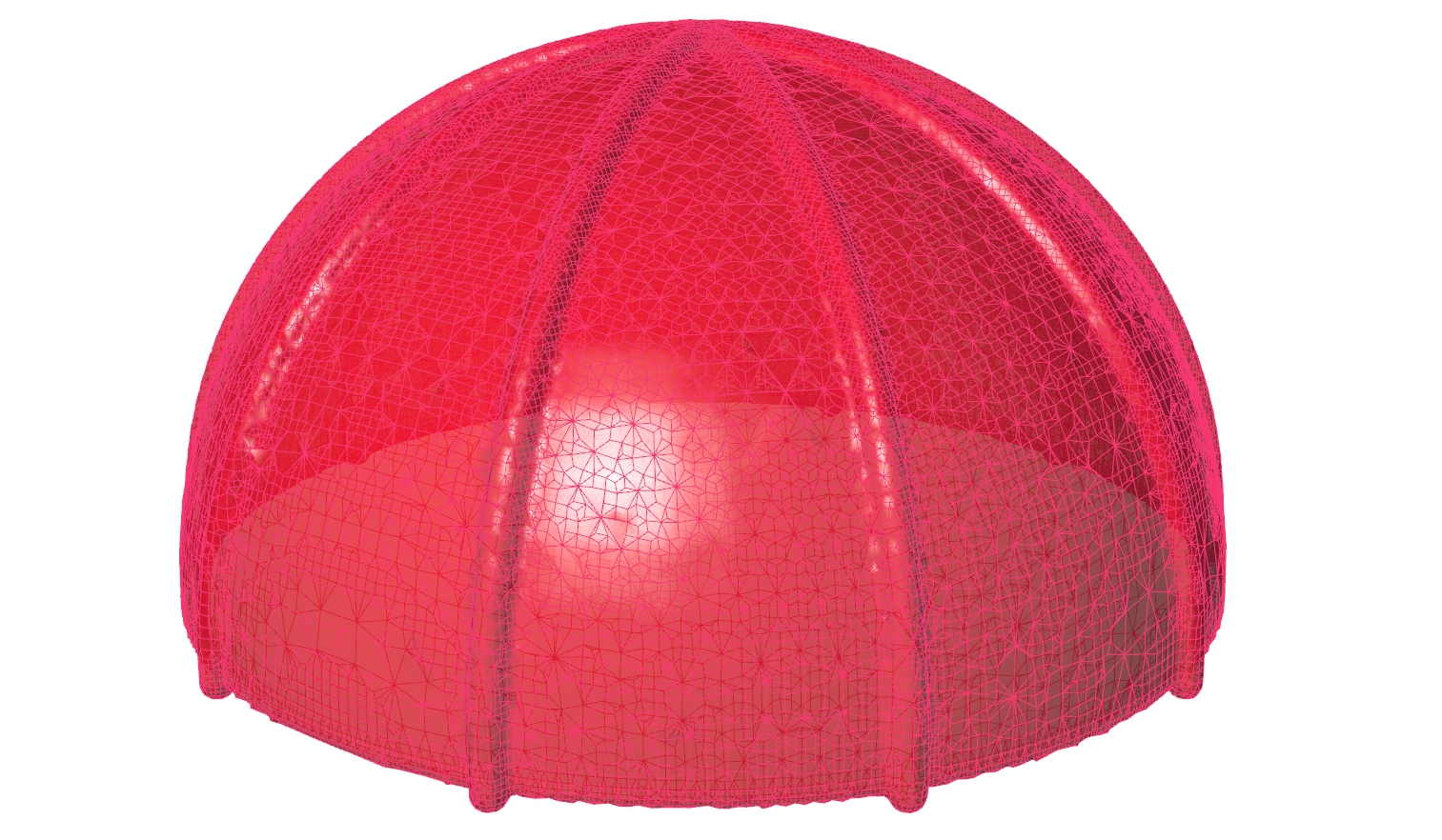
To illustrate the workflow, let’s create a hemisphere with some enclosed arches
that start from the bottom and meet at the top. For this, we first use the Sphere Sphere (Sph)
Inputs Base (B) Base plane Radius (R) Sphere radius Outputs Sphere (S) Resulting sphere 100 and attach a Brep | Plane Brep | Plane (Sec)
Inputs Brep (B) Base Brep Plane (P) Section plane Outputs Curves (C) Section curves Points (P) Section points  Surface Split (SrfSplit)
Inputs Surface (S) Base surface Curves (C) Splitting curves Outputs Fragments (F) Splitting fragments  List Item (Item)
Inputs List (L) Base list Index (i) Item index Wrap (W) Wrap index to list bounds Outputs Item (i) Item at {i'}

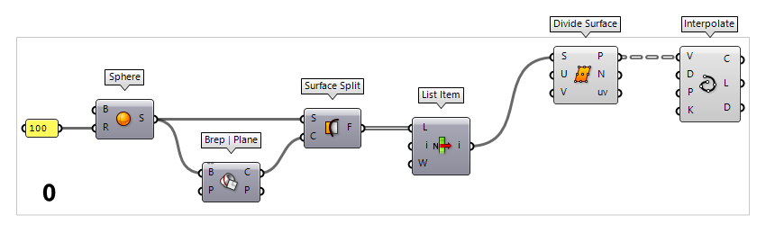
To create the arches, we first use a Divide Surface Divide Surface (SDivide)
Inputs Surface (S) Surface to divide U Count (U) Number of segments in {u} direction V Count (V) Number of segments in {v} direction Outputs Points (P) Division points Normals (N) Normal vectors at division points Parameters (uv) Parameter coordinates at division points  Interpolate (IntCrv)
Inputs Vertices (V) Interpolation points Degree (D) Curve degree Periodic (P) Periodic curve KnotStyle (K) Knot spacing (0=uniform, 1=chord, 2=sqrtchord) Outputs Curve (C) Resulting nurbs curve Length (L) Curve length Domain (D) Curve domain
1
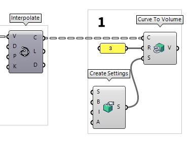
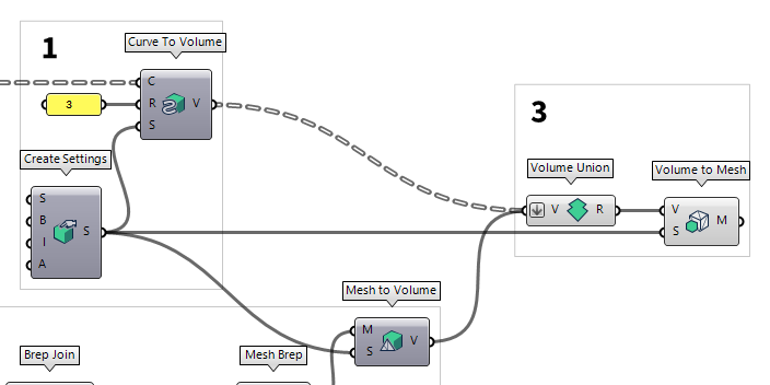
Convert curves to volumes
We use the Curve To Volume Curve To Volume (vCurve)
Inputs Curves (C) Curves Curve Radius (R) Supply one value or a list of values equal to the number of curves supplied Settings (S) Settings for converting different geometry types to and from volumes Outputs Volume (V) Volume geometry 3 is assigned with a Panel Panel
Panel
Dendro components that calculate volumetric objects need to have Create Settings Create Settings (vSettings)
Inputs Voxel Size (S) Size of voxels in the output volume Bandwidth (B) Desired radius in voxel units around the surface Isovalue (I) Crossing point of the volume that is considered the surface Adaptivity (A) Value range from 0-1. Higher adaptivities will allow more variation in polygon size, resulting in fewer polygons. Outputs Volume Settings (S) Global Volume Settings to be used
2
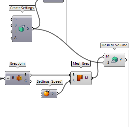
Convert surfaces to volumes
Surfaces have no thickness and can not be printed as they are; we have to give
them some thickness by creating an offset. Dendro has no component that handles
this automatically, just a general Mesh to Volume Mesh to Volume (vMesh)
Inputs Mesh (M) Base mesh Settings (S) Settings for converting different geometry types to and from volumes Outputs Volume (V) Volume geometry  Offset Surface (Offset)
Inputs Surface (S) Base surface Distance (D) Offset distance Retrim (T) Retrim offset Outputs Surface (S) Offset result -3, which is inwards in this example, to let the arch
profile stand out.
Now, there still is a gap at the bottom of the hemispheres, which we have to
close. This is done by attaching a Brep Edges Brep Edges (Edges)
Inputs Brep (B) Base Brep Outputs Naked (En) Naked edge curves Interior (Ei) Interior edge curves Non-Manifold (Em) Non-Manifold edge curves  Ruled Surface (RuleSrf)
Inputs Curve A (A) First curve Curve B (B) Second curve Outputs Surface (S) Ruled surface between A and B  Brep Join (Join)
Inputs Breps (B) Breps to join Outputs Breps (B) Joined Breps Closed (C) Closed flag for each resulting Brep

After this, we can use a Mesh Brep Mesh Brep (Mesh)
Inputs Brep (B) Brep geometry Settings (S) Settings to be used by meshing algorithm Outputs Mesh (M) Mesh approximation  Settings (Speed) (Jagged)
Inputs Outputs Settings (S) Coarse mesh settings
Mesh to Volume (vMesh)Inputs Mesh (M) Base mesh Settings (S) Settings for converting different geometry types to and from volumes Outputs Volume (V) Volume geometry
Create Settings (vSettings)Inputs Voxel Size (S) Size of voxels in the output volume Bandwidth (B) Desired radius in voxel units around the surface Isovalue (I) Crossing point of the volume that is considered the surface Adaptivity (A) Value range from 0-1. Higher adaptivities will allow more variation in polygon size, resulting in fewer polygons. Outputs Volume Settings (S) Global Volume Settings to be used
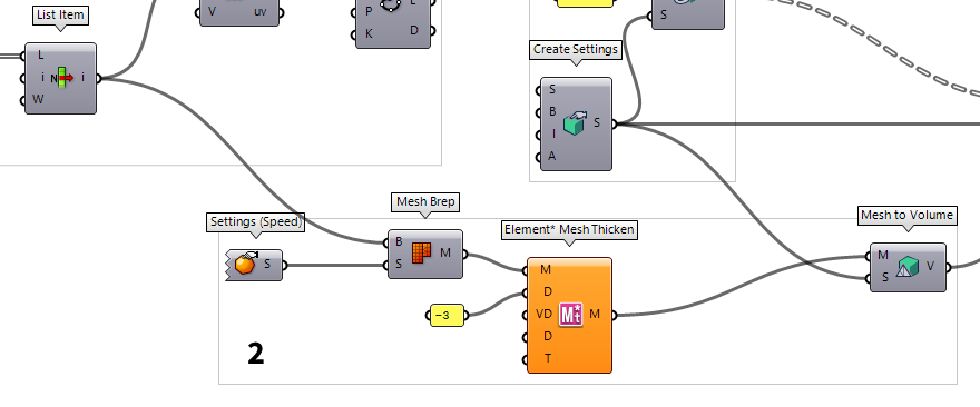
Alternative solution for thickening meshes
Instead of thickening the surface with several components, we can immediately convert the surface into a mesh. Various Grasshopper plugins that provide enhanced mesh functionalities offer something like mesh thickening or mesh offset. Those components allow us to set a distance and will close the resulting gaps automatically.
In the figure below, Element* Mesh Thicken Element* Mesh Thicken (MT)
Inputs Mesh (M) Input a polygon Mesh Distance (D) Input a float value to drive the offset distance PerVertex Data (VD) Input a list of float values to drive per vertex transformations Min and Max Values (D) Input a float domain range which drives the min and max values Type (T) Input integer Value list to specify value type (0 = Uniform | 1 = Per Vertex) Outputs Thickened Mesh (M) Outputs the thickened polygon mesh  Element* Mesh Combine & Clean (MC)
Inputs Mesh (M) Input single or multiple polygon Meshes Angle (A) Input a float value to specify WELD angle Merge Vertices (MV) Input boolean toggle - True Merges Identical Vertices | False Welds by Angle Flip Mesh (FM) Input boolean toggle - True Flips Mesh | False Leave Mesh Untouched Combine Type (CT) Input integer Value list to specify combine type (0 = Combine & Clean | 1 = Join Meshes) Outputs Mesh (M) Outputs a single cleaned Mesh object
3
Convert volumes back to a unified mesh
Once we have converted all desired parts of our model into voxel volumes, we use
Volume Union Volume Union (vUnion)
Inputs Volumes (V) Volumes to union Outputs Result (R) Union result  Volume to Mesh (mVolume)
Inputs Volume (V) Volume geometry Volume Settings (S) Global Volume Settings to be used Outputs Mesh (M) Mesh conversion of volume
Create Settings (vSettings)Inputs Voxel Size (S) Size of voxels in the output volume Bandwidth (B) Desired radius in voxel units around the surface Isovalue (I) Crossing point of the volume that is considered the surface Adaptivity (A) Value range from 0-1. Higher adaptivities will allow more variation in polygon size, resulting in fewer polygons. Outputs Volume Settings (S) Global Volume Settings to be used
Rhino
4
Export mesh from Grasshopper to Rhino
Now that we have a suitable meshed version of our model, the next step is to export it to Rhino. Before we do that, we need to double-check that our units in Rhino are set to millimeter. The document units are stated in the status bar.

If we need to change the unit settings, we can right-click the field and select
Unit Settings… and then set the Model units in the following window. With
the appropriate units we can now bake
Print it
Now we are done with the preparation of our model and the printing software will do the slicing and setup of the printer. Most manufactures offer tutorials on how to print with their software and how to operate the printer. Please follow their instructions for the actual printing.
The printing software will also check the integrity of the model. If errors occur, they usually provide some repair functions to straighten out minor hiccups. If this isn’t possible, it’s often better to avoid fiddling with the *.stl or *.3mf file and instead, look at the cause of the error and then tweak the Grasshopper code until the error disappears.
In cases where lots of support structure is needed to print the design object, we can cut it in Grasshopper into multiple parts with a plane, print them individually and glue them together after printing. Sometimes it also helps to turn the model upside down, so the pillars come last. An advanced process is to create the support structure in Grasshopper, too. This can be more efficient than the automatic generation by the printing software.