Everything we draw in Rhino or Grasshopper is part of a global Cartesian coordinate system, also called the world coordinate system. Therefore, every geometric shape within this system possesses defined coordinates and we can use Euclidean transformations to change their position and orientation is space. But sometimes, it’s cumbersome to calculate the new coordinates. Also, when we draw a shape, its generation mechanism aligns it to the world coordinate system’s axes.
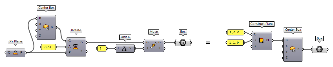
To ease both, the generation and transformation of geometric objects, there are construction planes, also called reference planes. Such a plane introduces a separate, local coordinate system and can be visioned as a drawing table set anywhere in space. For example, instead of creating a box in the world coordinate system and then rotate and move it to its destined position, we can also create a reference plane and then draw the box on this plane.
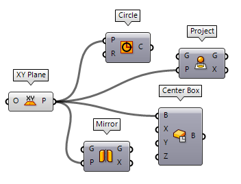
A lot of components in Grasshopper let us set a reference plane for either the creation of objects, transformations, or other operations. In general, it’s a better idea to generate construction planes first and then create the objects on top of them. In an algorithm, it’s easy to generate a unique plane for every object.
Construct planes
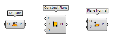
The ribbon group Vector > Plane hosts various components to create planes. For
example: XY Plane XY Plane (XY)
Inputs Origin (O) Origin of plane Outputs Plane (P) World XY plane  Construct Plane (Pl)
Inputs Origin (O) Origin of plane X-Axis (X) X-Axis direction of plane Y-Axis (Y) Y-Axis direction of plane Outputs Plane (Pl) Constructed plane  Plane Normal (Pl)
Inputs Origin (O) Origin of plane Z-Axis (Z) Z-Axis direction of plane Outputs Plane (P) Plane definition
You can find a couple more components to create planes with various input parameters. The components are self-explanatory.
Modify planes
The desired construction plane can also be obtained by altering an existing one.
The components are hosted in the same ribbon group Vector > Plane. For
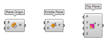
example, we can modify the origin of an existing plane with Plane Origin Plane Origin (Pl Origin)
Inputs Base (B) Base plane Origin (O) New origin point of plane Outputs Plane (Pl) Plane definition  Rotate Plane (PRot)
Inputs Plane (P) Plane to rotate Angle (A) Rotation (counter clockwise) around plane z-axis in radians Outputs Plane (P) Rotated plane  Flip Plane (PFlip)
Inputs Plane (P) Plane to adjust Reverse X (X) Reverse the x-axis direction Reverse Y (Y) Reverse the y-axis direction Swap axes (S) Swap the x and y axis directions Outputs Plane (P) Flipped plane
Again, there are a couple more components that do all kinds of adjustments with provided planes.
Deconstruct planes
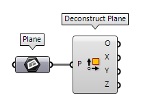
The component Deconstruct Plane Deconstruct Plane (DePlane)
Inputs Plane (P) Plane to deconstruct Outputs Origin (O) Origin point X-Axis (X) X-Axis vector Y-Axis (Y) Y-Axis vector Z-Axis (Z) Z-Axis vector
Construct planes with curves
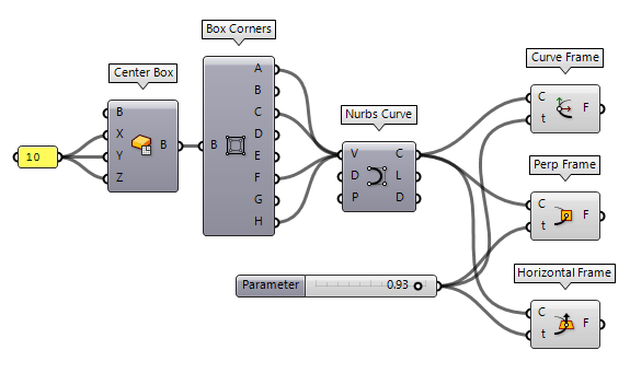
Besides vectors, we can also derive planes from curves. With given curve parameters t,
there are three option: Curve Frame Curve Frame (Frame)
Inputs Curve (C) Curve to evaluate Parameter (t) Parameter on curve domain to evaluate Outputs Frame (F) Curve frame at {t}  Perp Frame (PFrame)
Inputs Curve (C) Curve to evaluate Parameter (t) Parameter on curve domain to evaluate Outputs Frame (F) Perpendicular curve frame at {t}  Horizontal Frame (HFrame)
Inputs Curve (C) Curve to evaluate Parameter (t) Parameter on curve domain to evaluate Outputs Frame (F) Horizontal curve frame at {t}
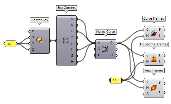
Instead of setting specific curve parameters, we can also use the related
components Curve Frames Curve Frames (Frames)
Inputs Curve (C) Curve to divide Count (N) Number of segments Outputs Frames (F) Curve frames Parameters (t) Parameter values at division points  Perp Frames (PFrames)
Inputs Curve (C) Curve to divide Count (N) Number of segments Align (A) Align the frames Outputs Frames (F) Curve frames Parameters (t) Parameter values at frame points  Horizontal Frames (HFrames)
Inputs Curve (C) Curve to divide Count (N) Number of segments Outputs Frames (F) Curvature frames Parameters (t) Parameter values at division points
Retrieve local coordinates
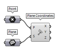
To find the local coordinates of a point on a construction plane, we can use Plane Coordinates Plane Coordinates (PlCoord)
Inputs Point (P) Input point System (S) Local coordinate system Outputs X coordinate (X) Point {x} coordinate Y coordinate (Y) Point {y} coordinate Z coordinate (Z) Point {z} coordinate
Retrieve planes from curves
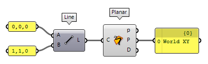
For planar curves, we can use Planar Planar (Planar)
Inputs Curve (C) Curve to evaluate Outputs Planar (p) Planarity of curve Plane (P) Curve plane Deviation (D) Deviation from curve plane
Retrieve planes from surfaces
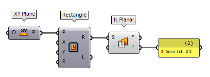
To find the plane of a planar surface, we can use Is Planar Is Planar (Planar)
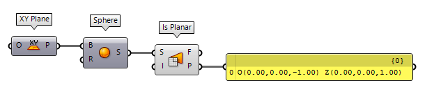
Inputs Surface (S) Surface to test for planarity Interior (I) Limit planarity test to the interior of trimmed surfaces Outputs Planar (F) Planarity flag of surface Plane (P) Surface plane
Using this component with a non-planar surface will return any plane, even when the surface was constructed with a base (construction) plane.
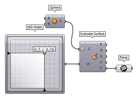
For non-planar surfaces, there is no unified plane and we need to evaluate a
point on the surface to get the plane at this position. To do so, we use Evaluate Surface Evaluate Surface (EvalSrf)
Inputs Surface (S) Base surface Point (uv) {uv} coordinate to evaluate Outputs Point (P) Point at {uv} Normal (N) Normal at {uv} U direction (U) U direction at {uv} V direction (V) V direction at {uv} Frame (F) Frame at {uv}
Using Planes in Transformations
Besides the basic transformations mentioned in the beginning of this how-to,
there are two powerful components to relocate geometric objects with reference
planes. The first one is Move To Plane Move To Plane (MoveToPlane)
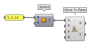
Inputs Geometry (G) Base geometry Plane (P) Target plane Above (A) Move when above plane Below (B) Move when below plane Outputs Geometry (G) Translated geometry Transform (X) Transformation data
The other component is Orient Orient (Orient)
Inputs Geometry (G) Base geometry Source (A) Initial plane Target (B) Final plane Outputs Geometry (G) Reoriented geometry Transform (X) Transformation data
