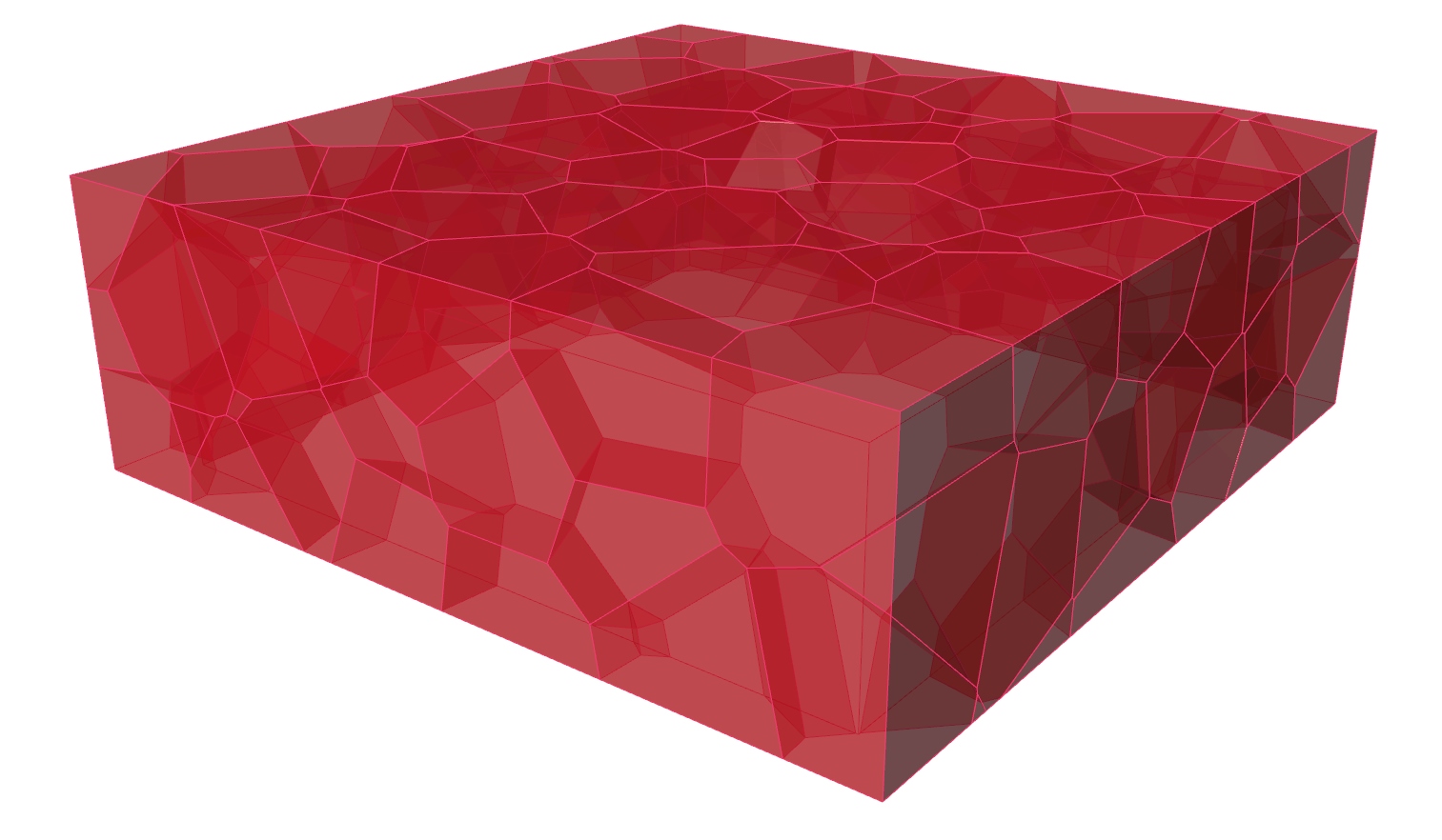
In this tutorial, we will continue with the basics of Grasshopper and create another space frame, for which the National Aquatics Center will serve as inspiration. The center was built for the 2008 Olympic Summer Games in Bejing, China, and was nicknamed the Water Cube because of its iconic appearance.
The structural design of the Water Cube is derived from the structure of foam or, to be more precise, from an idealized representation of foam: the Weaire-Phelan structure. This model describes the idealized distribution of equal-sized bubbles within a soap film. The bubbles strive to minimize their surface area per volume and thus to have the smallest possible surface tension.
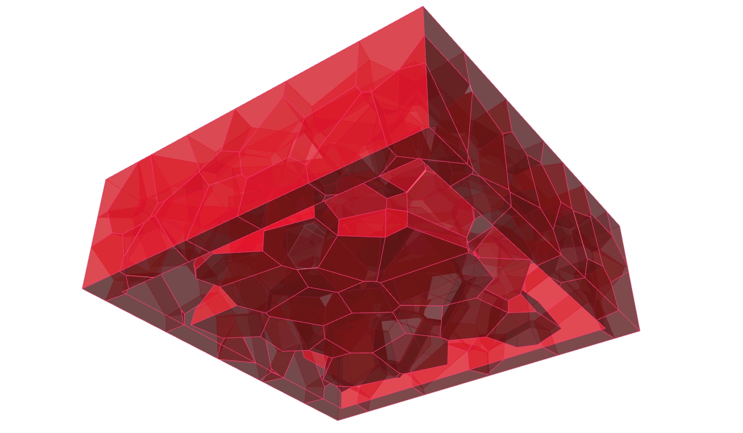
As you can see on the pictures below, the steel members of the space frame are
arranged along the edges of the intersections between the bubbles. Between them,
to cover the bubbles, there are ETFE cushions, which are also used
to collect passive solar energy. The National Aquatics Center was design and
built by a consortium of PTW
Architects,
Arup, CSCEC and
CCDI.


The key element for the design of the space frame is creating of the foam
structure. For this, we use a three-dimensional Voronoi tessellation, which
follows the same principles as the Voronoi diagram
Grasshopper
To keep calculations easy, we will use smaller dimensions and larger elements for our replica of the Water Cube.
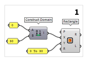
1
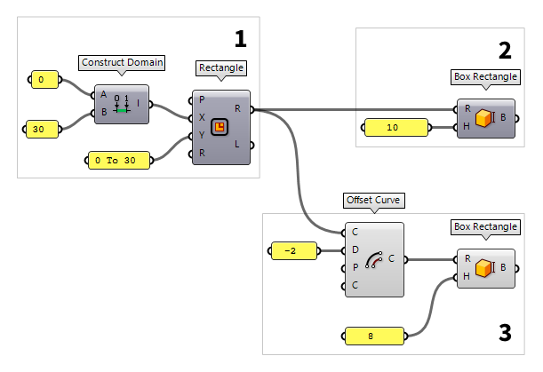
Define a ground plan
The first thing we do in Grasshopper is to define the volume of our cube. To do
this, we place the component Rectangle Rectangle (Rectangle)
Inputs Plane (P) Rectangle base plane X Size (X) Dimensions of rectangle in plane X direction. Y Size (Y) Dimensions of rectangle in plane Y direction. Radius (R) Rectangle corner fillet radius Outputs Rectangle (R) Rectangle Length (L) Length of rectangle curve
A domain can be created with the component Construct Domain Construct Domain (Dom)
Inputs Domain start (A) Start value of numeric domain Domain end (B) End value of numeric domain Outputs Domain (I) Numeric domain between {A} and {B}  Panel
Panel0 and the other with
30. A shortcut to create a domain is to write 0 To 30 directly into a Panel
Panel
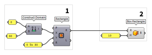
2
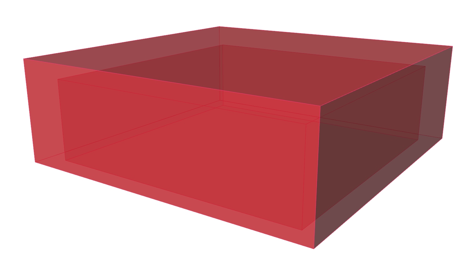
Create the outer building volume
To create a volume with the just defined rectangle, we use Box Rectangle Box Rectangle (BoxRec)
Inputs Rectangle (R) Base rectangle Height (H) Box height Outputs Box (B) Resulting box 10), the component will automatically create a
domain from 0 to the provided number; in this case the domain will be 0 To 10.
3
Create the inner volume
To create a second, smaller volume, we use the component Offset Curve Offset Curve (Offset)
Inputs Curve (C) Curve to offset Distance (D) Offset distance Plane (P) Plane for offset operation Corners (C) Corner type flag. Possible values:
none = 0
sharp = 1
round = 2
smooth = 3
chamfer = 4Outputs Curve (C) Resulting offsets
Box Rectangle (BoxRec)Inputs Rectangle (R) Base rectangle Height (H) Box height Outputs Box (B) Resulting box
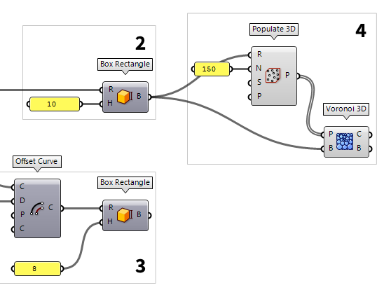
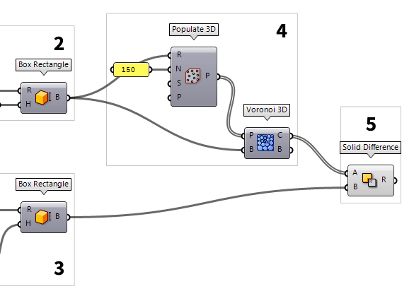
4
Generate the Voronoi structure
Next, we want to generate a 3D Voronoi diagram between the two volumes. For
this, we need the points around which the cells will be generated. We get them
from creating random points in our larger volume with Populate 3D Populate 3D (Pop3D)
Inputs Region (R) Box that defines the 3D region for point insertion Count (N) Number of points to add Seed (S) Random seed for insertion Points (P) Optional pre-existing population Outputs Population (P) Population of inserted points
Now, the just created points will serve us as input P (Points) on a Voronoi 3D Voronoi 3D (Voronoi³)
Inputs Points (P) Points for Voronoi diagram Box (B) Optional diagram boundary Outputs Cells (C) Cells of the 3D Voronoi diagram Boundary (B) List of boolean values indicating for each cell whether it is part of the original boundary
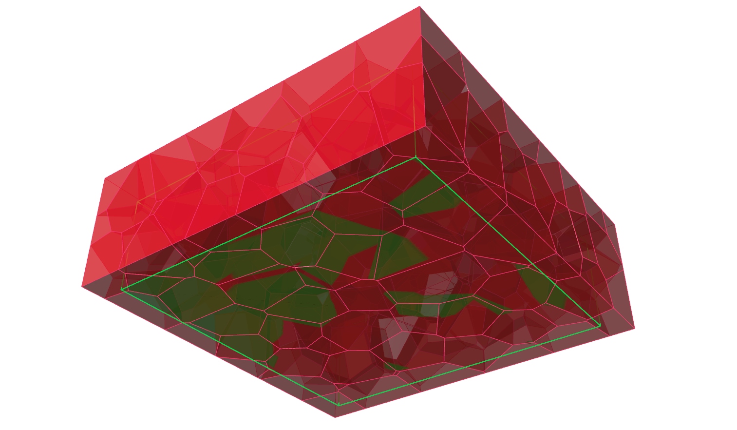
5
Cut the Voronoi cells
After having a look at the cells in Rhino, we notice that they fill the whole
volume, even the inner, smaller one, which is not what we desire. Therefore, we
have to cut the inner volume out of the Voronoi foam. For this we use Solid Difference Solid Difference (SDiff)
Inputs Breps A (A) First Brep set Breps B (B) Second Brep set Outputs Result (R) Difference result
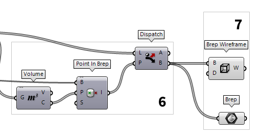
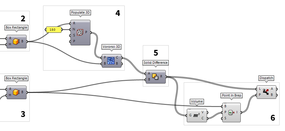
6
Select the desired results
The cutting process worked for all cells that touched the inner volume, but we
still have some isolated, intact cells inside the smaller volume. Let’s
filter them out: For this we determine the center point of each Brep with Volume Volume (Volume)
Inputs Geometry (G) Closed brep or mesh for volume computation Outputs Volume (V) Volume of geometry Centroid (C) Volume centroid of geometry  Point In Brep (BrepInc)
Inputs Brep (B) Brep for inclusion test Point (P) Point for inclusion test Strict (S) If true, then the inclusion is strict Outputs Inside (I) True if point is on the inside of the Brep.
Now, we use Dispatch Dispatch (Dispatch)
Inputs List (L) List to filter Dispatch pattern (P) Dispatch pattern Outputs List A (A) Dispatch target for True values List B (B) Dispatch target for False values
Solid Difference (SDiff)Inputs Breps A (A) First Brep set Breps B (B) Second Brep set Outputs Result (R) Difference result
7
Extract the structural elements
In the final step, we can bundle the Voronoi cells inside a Brep Brep (Brep)
 Brep Wireframe (Wires)
Inputs Brep (B) Base Brep Density (D) Wireframe isocurve density Outputs Wireframe (W) Wireframe curves